당신은 주제를 찾고 있습니까 “ug 16 asme – Shell thickness calculation of pressure vessel (part 1)“? 다음 카테고리의 웹사이트 https://ro.taphoamini.com 에서 귀하의 모든 질문에 답변해 드립니다: ro.taphoamini.com/wiki. 바로 아래에서 답을 찾을 수 있습니다. 작성자 FN Engineering 이(가) 작성한 기사에는 조회수 29,486회 및 좋아요 454개 개의 좋아요가 있습니다.
Table of Contents
ug 16 asme 주제에 대한 동영상 보기
여기에서 이 주제에 대한 비디오를 시청하십시오. 주의 깊게 살펴보고 읽고 있는 내용에 대한 피드백을 제공하세요!
d여기에서 Shell thickness calculation of pressure vessel (part 1) – ug 16 asme 주제에 대한 세부정보를 참조하세요
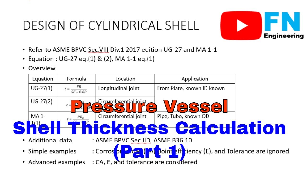
ASME Tutorial or Pressure Vessel Design: Shell thickness calculation of pressure vessel equipment (part 1)
Chapter Lists:
Opening 00:00
Overview 00:23
Symbol and Definition 02:36
Simple Study Case 04:56
Study Case or Example 1 05:57
Study Case or Example 2 09:37
Advanced Study Case 13:23
Closing 13:52
Step by step pressure vessel design calculation examples by using International standard ASME Section VIII Division 1
Outline video
– Overview shell thickness calculation ( references, equation, data required, simple study cases)
– Symbol and definition used for shell thickness calculation
– Shell thickness calculation formula ( paragraph UG-27, paragraph MA-1)
– Shell thickness calculation example: plate thickness calculation, pipe thickness calculation
Source or Reference: ASME Section VIII Division 1, ASME Standards, ASME Section IID, ASME B36.10
Spreadsheet link: http://bit.ly/FNEngineeringFile
PDF explanation link: https://www.studypool.com/services/16428326
List of Playlist:
– Full Video (First Edition) : https://youtube.com/playlist?list=PL8Boroy7Xr1ljIRymcc6jbNPM8At1oATi
– Pressure Vessel Basic Design : https://youtube.com/playlist?list=PL8Boroy7Xr1kYCDdeocvEScFJul3eGHJu
– Pressure Vessels Series : https://youtube.com/playlist?list=PL8Boroy7Xr1l9zoCHpCdBy93nZwIODZY7
– Shell and Tube Heat Exchangers : https://youtube.com/playlist?list=PL8Boroy7Xr1mIDVrtAImFiwGxYPKZMYrw
– ASME B31.3 : https://youtube.com/playlist?list=PL8Boroy7Xr1mS16IeRzd69P_TVM11fqur
– Design of Material : https://youtube.com/playlist?list=PL8Boroy7Xr1neeSLkmiLVSdWnzPISMv6I
– Shell Calculation : https://youtube.com/playlist?list=PL8Boroy7Xr1nrIj0ffbAaz6ZXSNclowdS
– External Pressure Design Calculation : https://youtube.com/playlist?list=PL8Boroy7Xr1lq81BJK5pA9Xj7LO1LWI1G
– Thickness Calculation : https://youtube.com/playlist?list=PL8Boroy7Xr1miYdr5K0pSPIOaIaSB33R8
– Welded Joints, Radiograhy, Joint Efficiencies : https://youtube.com/playlist?list=PL8Boroy7Xr1l32gwSh9Xl8eCA7OwR7one
– Type of Pressure Design Calculation : https://youtube.com/playlist?list=PL8Boroy7Xr1nCU6X5hoqE-i3cCTEBFqXg
– Nozzles, Reinforcement, Flanges, and Fittings : https://youtube.com/playlist?list=PL8Boroy7Xr1lW4bVEKozOVQsY7ehqFXeK
– Database Series : https://youtube.com/playlist?list=PL8Boroy7Xr1kHfoMKB2uq3KVMYzybENov
– Study Cases : https://youtube.com/playlist?list=PL8Boroy7Xr1nxdnarQezINL8tDKRupuMM
– Question and Answer : https://youtube.com/playlist?list=PL8Boroy7Xr1nWAhu3YurLtnRotOSzZSoT
Tools Riset Keyword: https://www.tubebuddy.com/FNEngineering (affiliate)
** Affiliate disclaimer: some of the above links may be affiliate links, which may generate us a sales commission
ug 16 asme 주제에 대한 자세한 내용은 여기를 참조하세요.
UG-16(b) value for nozzle neck thickness – Eng-Tips
Since you reference UG-16(b) and UG-45, I was under the impression that you were using the ASME Boiler and Pressure Vessel Code Section VIII …
Source: www.eng-tips.com
Date Published: 11/15/2021
View: 855
Skip UG-16(b) Minimum Thickness Calculation – PV Elite – Help
There are certain exemptions from this requirement such as in the case of heat exchanger tubes. Refer to the ASME Section VIII, Division -1, UG-16(b) for …
Source: docs.hexagonppm.com
Date Published: 8/23/2022
View: 8606
ASME VIII-1 : Different application of UG16 Min. Thickness
On case [1], PVElite report stated 1.5 mm as minimum shell thickness (UG-16 case) since calculated thickness using UG-27 is lower. On case [2], …
Source: forums.coade.com
Date Published: 10/11/2021
View: 9385
UG-16 일반 사항 (2019년 2월 10일) – Daum 블로그
최소 두께에 관하여 ASME 는 어떻게 정리하고 있는지 알아보면… UG-16 GENERAL ⒜ Pressure vessel 과 Vessel part 는 아래에 나열된 내용과 …
Source: blog.daum.net
Date Published: 11/22/2021
View: 6251
Sample Vessel Calculations
Not all ASME VIII-1 requirement are covered in the calculation sheets … The UG-16(b) minimum thickness requirement has not been taken into …
Source: dadospdf.com
Date Published: 6/2/2021
View: 6932
주제와 관련된 이미지 ug 16 asme
주제와 관련된 더 많은 사진을 참조하십시오 Shell thickness calculation of pressure vessel (part 1). 댓글에서 더 많은 관련 이미지를 보거나 필요한 경우 더 많은 관련 기사를 볼 수 있습니다.
주제에 대한 기사 평가 ug 16 asme
- Author: FN Engineering
- Views: 조회수 29,486회
- Likes: 좋아요 454개
- Date Published: 2019. 11. 21.
- Video Url link: https://www.youtube.com/watch?v=B-ZfwAJuNwY
UG-16(b) value for nozzle neck thickness
INTELLIGENT WORK FORUMS
FOR ENGINEERING PROFESSIONALS Contact US FIRST NAME *
LAST NAME *
EMAIL *
MESSAGE *
ADDITIONAL DETAILS
Thanks. We have received your request and will respond promptly. Log In Come Join Us! Are you an
Engineering professional?
Join Eng-Tips Forums! Talk With Other Members
Be Notified Of Responses
To Your Posts
To Your Posts Keyword Search
One-Click Access To Your
Favorite Forums
Favorite Forums Automated Signatures
On Your Posts
On Your Posts Best Of All, It’s Free! Join Us! *Eng-Tips’s functionality depends on members receiving e-mail. By joining you are opting in to receive e-mail. Posting Guidelines
Students Click Here Promoting, selling, recruiting, coursework and thesis posting is forbidden. Eng-Tips Posting Policies
Contact US Related Projects
UG-16(b) value for nozzle neck thickness thread292-301632 Forum Search FAQs Links MVPs Menu Forum
Search
FAQs
Links
MVPs UG-16(b) value for nozzle neck thickness UG-16(b) value for nozzle neck thickness Alaitz (Mechanical) (OP) 27 Jun 11 08:59 Hello everybody!
I’m calculating a nozzle neck thickness per UG-45 and I’m not sure about which is the minimum thickness specified by UG-16(b).
My equipment works with steam / water and the material is in the Table UCS-23, then for shell and heads the minimum thickness is 2.4 mm per UG-16(b)(4).
Do I have to use this same value for nozzles? or Can I use 1.6 mm? In the UG-16(b) only speaks about shells and head.
Thank you very much! RE: UG-16(b) value for nozzle neck thickness jamesl (Mechanical) 28 Jun 11 11:35 The only way you can use 1.6mm as your nozzle wall is that the nozzle pipe size is so small that the standard pipe thickness is 1.6mm and there is no C.A. There is only one pipe size that meets this requirement – 1/8″ nozzle. Otherwise you have to have 2.4mm+C.A. for minimum nozzle thickness. RE: UG-16(b) value for nozzle neck thickness Alaitz (Mechanical) (OP) 29 Jun 11 03:45 Thank you very much Jamesl!! RE: UG-16(b) value for nozzle neck thickness Alaitz (Mechanical) (OP) 29 Jun 11 07:36 One more question…
I have take a corrosion allowance of 3 mm for shell / heads and 1.5 mm for the nozzles (as is said in the Heat Exchange Institute Standard for Deaerators).
In the calculation of the values of UG-16(b), UG-45(b)(1) and UG-45(b)(2), which value of CA shall be use, 3 or 1.5 mm?
Thanks in advance!! RE: UG-16(b) value for nozzle neck thickness vpl (Nuclear) 29 Jun 11 09:18
Two questions:
1) What Code are you using to design this vessel? Or, more importantly, what Code did you tell your customer that you were going to use to design the vessel? Since you reference UG-16(b) and UG-45, I was under the impression that you were using the ASME Boiler and Pressure Vessel Code Section VIII.
2) If you are designing to ASME Section VIII, why are you going to other standards (such as the Heat Exchanger Institute Standard) to pick minimum values? Should you not be using the minimum value from the Code?
From both your first question and your second, it appears that you are trying to minimize the amount of steel being used while still claiming to meet the Code — and are looking for this forum to help justify your actions. AlaitzTwo questions:1) What Code are you using to design this vessel? Or, more importantly,that you were going to use to design the vessel? Since you reference UG-16(b) and UG-45, I was under the impression that you were using the ASME Boiler and Pressure Vessel Code Section VIII.2) If you are designing to ASME Section VIII, why are you going to other standards (such as the Heat Exchanger Institute Standard) to pick minimum values? Should you not be using the minimum value from the Code?From both your first question and your second, it appears that you are trying to minimize the amount of steel being used while still claiming to meet the Code — and are looking for this forum to help justify your actions. Patricia Lougheed
******
Please see FAQ731-376: Eng-Tips.com Forum Policies: Eng-Tips.com Forum Policies for tips on how to make the best use of the Eng-Tips Forums. RE: UG-16(b) value for nozzle neck thickness SnTMan (Mechanical) 29 Jun 11 09:44 Alaitz, in my opinion your nozzle min thickness is governed by UG-16(b)(4), 2.5 mm. Note that UG-45 refers specifically to UG-16, and since your class of work falls under UG-16(b)(4) you are bound by it.
As for the corrosion allowances, apply 3 mm to the UG-45 tb1, tb2 thickness, apply 1.5 mm to the UG-45 ta and tb3 thicknesses.
I believe you are correct, in the absence of specified corrosion allowances to use HEI guidelines. Sec VIII, Div 1 so far as I know does not specify a corrosion allowance, only that it be considered.
Regards,
Mike RE: UG-16(b) value for nozzle neck thickness Alaitz (Mechanical) (OP) 30 Jun 11 02:52 Thank you very much Mike! I will use the CA coeficients as you say, although I think is not so logical ;D
Ummm… How you know that you have to take the CA of the vessel instead of the CA of the nozzle? In the ASME only is talk about the thicness calculation without the CA.
I know you are right (I have see it in a very very old and not official documentation too) but, why?
Patricia, as Mike has said the ASME and the HEI codes are not mutually exclusive. ASME don’t say which must be de CA value and the HEI don’t say how to calculate the thickness. I know that is a bad idea to use two codes like ASME and AD-Merkblatter, I understand your concern and I thank you to coment because it would have taken place.
Of curse, i want to take the minimum thickness (like everybody I understand, otherwise why are so much formulas in the ASME? It will be more easy to use the more restrictive one) but, always by the side of safety.
On the other hand, I will like to thank you all for this forum, is the first time I ask something but, i have use it so many times to solve doubts.
Finally, sorry for my poor English.
See you! RE: UG-16(b) value for nozzle neck thickness SnTMan (Mechanical) 30 Jun 11 09:22 Quote: Ummm… How you know that you have to take the CA of the vessel instead of the CA of the nozzle? In the ASME only is talk about the thicness calculation without the CA.
You just use relevant corrosion allowance for the relevant part. In my class of work it is not uncommon for an owner specification to require greater CA for nozzles than for the vessel. It just depends on the service and life desired.
Code nomenclature for sizes nearly always states “exclusive of corrosion allowance” or “in the corroded condition”.
Regards,
Mike You just use relevant corrosion allowance for the relevant part. In my class of work it is not uncommon for an owner specification to require greater CA for nozzles than for the vessel. It just depends on the service and life desired.Code nomenclature for sizes nearly always states “exclusive of corrosion allowance” or “in the corroded condition”.Regards,Mike RE: UG-16(b) value for nozzle neck thickness Alaitz (Mechanical) (OP) 1 Jul 11 08:00 I think that I have explain incorrectly. Im not asking how much should be de CA value, always I take 3mm for this type of equipment (maybe you have understand this?).
Say in another way:
The formulas in the ASME (commonly) are without CA and, after you calculate the value of t you add the CA.
In the UG-45 you are calculating the thickness of the nozzle, so I calculated ta, tb1, tb2, tb3, tb4 or t16 and after I added the CA of the nozzle (becase I’m calculating the thickness of the nozzle).
Now, I now this is wrong but, I don’t understand why.
In your case, that CA of the nozzle is greater than the CA of the vessel, do you use the CA of the vessel to calculate UG-45 tb1, tb2? I shold use the CA of the nozzle.
Don’t worry. I like to understand why I do something but, is suficient to know which is the correct procedure.
Thanks. RE: UG-16(b) value for nozzle neck thickness SnTMan (Mechanical) 1 Jul 11 09:36 Alaitz, suppose you had, say, a CS vessel with CA with a SS nozzle with zero CA.
When calculating tb1, tb2 and UG-16 thickness the vessel CA would have to be added, rather than zero CA.
When calculating ta and tb3 nozzle CA is added, in this case zero, rather than the vessel CA.
The UG-45 thicknesses are the minimum required in the new condition, thus the relevant CA is added to the relevant component.
As a check I ran this problem in one commercial software that I use and it applied the CA’s in this way.
Hope this helps.
Mike
RE: UG-16(b) value for nozzle neck thickness Alaitz (Mechanical) (OP) 8 Jul 11 03:44 Sorry, I have been out this week.
Mike, I’m very grateful to you for your detailed explanations, it have been very useful.
See you!!! Red Flag This Post Please let us know here why this post is inappropriate. Reasons such as off-topic, duplicates, flames, illegal, vulgar, or students posting their homework.
Cancel Red Flag Submitted Thank you for helping keep Eng-Tips Forums free from inappropriate posts.
The Eng-Tips staff will check this out and take appropriate action. Close Reply To This Thread Posting in the Eng-Tips forums is a member-only feature. Click Here to join Eng-Tips and talk with other members! Already a Member? Login
Resources Low-Volume Rapid Injection Molding With 3D Printed Molds Learn methods and guidelines for using stereolithography (SLA) 3D printed molds in the injection molding process to lower costs and lead time. Discover how this hybrid manufacturing process enables on-demand mold fabrication to quickly produce small batches of thermoplastic parts. Download Now Design for Additive Manufacturing (DfAM) Examine how the principles of DfAM upend many of the long-standing rules around manufacturability – allowing engineers and designers to place a part’s function at the center of their design considerations. Download Now Industry Perspective: Education and Metal 3D Printing Metal 3D printing has rapidly emerged as a key technology in modern design and manufacturing, so it’s critical educational institutions include it in their curricula to avoid leaving students at a disadvantage as they enter the workforce. Download Now Taking Control of Engineering Documents This ebook covers tips for creating and managing workflows, security best practices and protection of intellectual property, Cloud vs. on-premise software solutions, CAD file management, compliance, and more. Download Now
ASME VIII-1 : Different application of UG16 Min. Thickness
Topic Options #30613 – 03:43 AM ASME VIII-1 : Different application of UG16 Min. Thickness SK Tan
Member
Registered: 01/15/09
Posts: 66
Loc: Malaysia
We have an example where PVElite 2009 (Jun Built) applied different UG-16 min. thickness on report of :
1] Internal pressure (Shell)
2] Nozzle
On case [1], PVElite report stated 1.5 mm as minimum shell thickness (UG-16 case) since calculated thickness using UG-27 is lower.
On case [2], PVElite report applied 1.5875 mm (UG-16 b) at UG45 area.
Refer to ASME VIII-1 2007 Editin Add 08, UG-16 b stated 1/16 Inch [ 1.5 ] excluding any corrosion allowance is minimum for shell and head after forming.
1/16″ = 1.5875 mm by normal conversion practice. (25.4 / 16)
But ASME code’s rule is only 1.5 mm if use S.I. unit, and shall be applied consistently.
We are wondering why PVElite applied 1.5 mm and 1.5875 mm in-consistently on same model.
Our case is right at border case now. Result of analysis is clean if PVElite applied 1.5 mm consistently on shell and nozzle calculation.
Wish Coade can advise something about this.
Thank you!
Top #30725 – 04:10 AM Re: ASME VIII-1 : Different application of UG16 Min. Thickness Re: SK Tan] Mukesh
Member
Registered: 11/12/06
Posts: 125
Loc: Ahmedabad, Gujarat, India Hi SK Tan,
You are correct that there is a problem in application of UG-16 min. thickness in shell and nozzle design as it using different values.
To the best of my knowledge, The problem is already brought to their notice earlier and also corrected by COADE and is going to come in next version of PV ELITE i.e. PV Elite 2010.
Hope this will help you soon. Meanwhile you can have manual calculations of nozzles for the same or you can explain to your client during discussions.
Thanks.
Mukesh
Top #32210 – 10:34 PM Re: ASME VIII-1 : Different application of UG16 Min. Thickness Re: Mukesh] SK Tan
Member
Registered: 01/15/09
Posts: 66
Loc: Malaysia To Coade,
Coade just launched PVElite 2010. We are waiting for the installation disc.
Meanwhile, check with Coade, has the above UG16 error be fixed on PVElite 2010 as informed by Mukesh?
We could not see this on the PVElite 2010 changes list.
Thank you!
S K Tan
Top #32221 – 08:06 AM Re: ASME VIII-1 : Different application of UG16 Min. Thickness Re: SK Tan] Ray_Delaforce
Member
Registered: 01/02/03
Posts: 743
Loc: Houston, TX Hello Folks
In the 2010 version of PV Elite this issue has been fixed. If the thickness of a component is less that 1.5 mm, and you have chosen metric units, and set the configuration dialogue screen to consistent metric units, you will get this note:
Note: The thickness required was less than the Code Minimum, therefore
the Code Minimum value of 1.5000 mm per UG-16 will be used.
One of the problems we have is that people do not use SI Metric units, and PV Elite can get confused. For example, in many countries, such as India, stresses are designated in kgf/cm^2. This is not a metric unit. Other counties may state pressure in psi, and stresses in N/mm^2. PV Elite has no problem with proper SI Metric units, but may not be able to handle other units. Make sure you set the configuration dialogue screen to consistent metric units.
Sincerely,
Ray Delaforce
CADWorx & Analysis Solutions
Hexagon PPM
_________________________Sincerely,Ray DelaforceCADWorx & Analysis SolutionsHexagon PPM
Top #32242 – 11:50 AM Re: ASME VIII-1 : Different application of UG16 Min. Thickness Re: Ray_Delaforce] Mandeep Singh
Member
Registered: 12/15/99
Posts: 600
Loc: Houston, Tx, USA
http://info.coade.com/content/PVEliteRelease This link provides the details about the new enhancements in PV Elite 2010,
Best Regards,
Mandeep Singh
CADWorx & Analysis Solutions
Hexagon PPM
_________________________Best Regards,Mandeep SinghCADWorx & Analysis SolutionsHexagon PPM
Top
Tweet
Preview
Hop to: Analysis Solutions —— CAESAR II PV Elite TANK CADWorx Solutions —— CADWorx Plant CADWorx ISOGEN CADWorx P&ID CADWorx Equipment CADWorx Structure CADWorx Design Review CADWorx fieldPipe CADWorx Draft Pro CADWorx Steel General —— General ICAS Dealers Mandeep Singh, Ray_Delaforce, Scott_Mayeux Moderator: Luis Sanjuan Who’s Online 1 registered (Gino2010), 31 Guests and 1 Spider online. Key: Admin , Global Mod , Mod August Su M Tu W Th F Sa 1 2 3 4 5 6 7 8 9 10 11 12 13 14 15 16 17 18 19 20 21 22 23 24 25 26 27 28 29 30 31 Forum Stats 12016 Members
14 Forums
16882 Topics
74777 Posts
Max Online: 303 @ 11:58 PM Top Posters (30 Days) Richard Ay 16 Borzki 14 Michael_Fletcher 7 nir 5 vacsworld 4
압력용기 와 ASME
최소 두께에 관하여 ASME 는 어떻게 정리하고 있는지 알아보면…
UG-16 GENERAL
⒜ Pressure vessel 과 Vessel part 는 아래에 나열된 내용과 Specific requirements for Design given in the applicable
parts of subsections B and C 의 내용을 따라주세요.
⒝ Minimum Thickness of Pressure Retaining Components.
아래에 명기된 special provision을 제외하고는, Product form 과 material 에 관계없이
Shell 과 Heads 의 최소두께는 부식 허용값을 제외한 상태에서 1.5mm (Minimum)
이어야 한다.
⑴ the minimum thickness does not apply to heat transfer plates of plate-
type heat exchanger.
⑵ the Minimum thickness does not apply to the inner pipe of double pipe
heat exchangers nor to pipes and tubes that are enclosed and protected
from mechanical damaged by a shell, casing, or ducting, where such pipes
or tube are NPS 6 (DN150) and less.
This exemption applies whether or not the outer pipe, shell, or protective
element is constructed to code rules.
When the outer protective elements is not provided by the Manufacturer as
part of the vessel, the manufacturer shall note this on the Manufacturer’s
Data report, and the owner or his designated agent shall be responsible to
assure that the required enclosures are installed prior to operation.
Where pipes and tubes are fully enclosed, consideration shall be given to
avoiding buildup of pressure within the protective chamber due to tube/pipe
leak.
All other pressure parts of these heat exchangers that are constructed to
code rules must meet 1.5mm (Min) thickness requirements.
⑶ the Min-thickness of shells and heads of unfired steam boilers shall be 6mm
exclusive of any Corrosion Allowance.
⑷ the minimum thickness of shells and heads used in compressed air service,
steam service, and water service, made from materials listed in Table
UCS-23, shall be 2.5mm exclusive of any corrosion allowance.
⑸ this minimum thickness does not apply to the tubes in air cooled and cooling
tower heat exchangers if all the following provisions are met :
㈎ the tubes shall not be used for tethal UW-2⒜ service application.
㈏ the tubes shall be protected by fins or other mechanical means
㈐ tue tube outside diameter shall be a minimum of 10mm and a maximum of
38mm
㈑ the minimum thickness used shall not be less than that calculated by the
formulas given in UG-27 or 1-1 and in no case less than 0.5mm
⒞ Plate under-tolerance.
⑴ plate material shall not be ordered with a nominal thickness thinner than the
design thickness.
⑵ Plate material with an actual thickness less than the design thickness shall not
be used unless the difference in thickness is less than the smaller of 0.3mm
or 6% of the deign thickness (See UG-90 ⒝ ⑹ )
⑶ if plate material is ordered to a specification that allows an under-tolerance
greater than the smaller of 0.3 or 6% of the nominal thickness, the thickness
of the plate material will meet the requirement of ⑵ when used.
⒟ Pipe under-tolerance.
If pipe or tube is ordered by its nominal wall thickness, the manufacturing
under-tolerance on wall thickness shall be taken into account except for nozzle
wall reinforcement area requirements in accordance with UG-37 and UG-40.
The minimum under-tolerance are given in the several pipe and tube
specification listed in the applicable table in subsection C.
⒠ Corrosion Allowance in Design Formulas.
The dimensional symbols used in all design formulas through out this division
represent dimensions in the corroded condition.
⒡ Examples showing the application of the design rules of this division are
contained in ASME PTB-4, ASME Sec. VIII. Div.1 example problem manual.
Feb.10. 2019. J.H.Jang
[PDF] ASME9 FEA Report
ASME9 FEA Report
BAIXAR PDF
Descrição do Produto
Sample Vessel Calculations
These calculation sheets are for educational purposes only. These calculation sheets are recommended for the following: – Preliminary determination of wall thickness – Preliminary material estimates – Estimating volumes and weights Not all ASME VIII-1 requirement are covered in the calculation sheets
Notes Regarding Sample Vessel Calculations: – Nozzle N3 is not calculated due to its small size. – Nozzle N2 uses a thin wall (SCH 5) to demonstrate the use of a repad.
PVE – 3247 17-Feb-09 Revision 0 Ben Vanderloo
Pressure Vessel Engineering Ltd.
1
Finite Element Analysis ASME Code Calculations Canadian Vessel Registration Vessel Modeling and Drafting
2 3
4 5 6
7 8 9 10 11 12 13 14 15 16 17 18 19 20 21 22 23 24 25 26 27 28 29 30 31 32 33 34 35 36 37 38 39 40 41 42 43 44
Material Database ver E4.00
Page 1 of 8
Material Properties: 400.0 Temp [°F] – maximum design temperature Material
Ambient Design Strength Strength Max ºF
SA-36 Plate 16,600 SA-106 B Seamless Pipe 17,100 SA-234 WPB Fittings 17,100 SA-105 Forging 20,000 SA-516 70 Plate 20,000 SA-414 G Sheet 21,400 SA-213 TP316L Sms Tube 16,700 SA-240 316L Plate 16,700 SA-312 TP316L Sms. and Wld. Pipe 16,700 SA-403 316L Sms and Weld Fittings 16,700 SA-479 316L Bar 16,700 SA-213 TP316 Sms Tube 20,000 SA-240 316 Plate 20,000 SA-312 TP316 Sms. and Wld. Pipe 20,000 SA-403 316 Sms and Weld Fittings 20,000 SA-479 316 Bar 20,000 SA-213 TP304L Sms Tube 16,700 SA-240 304L Plate 16,700 SA-312 TP304L Sms. and Wld. Pipe 16,700 SA-403 304L Sms and Weld Fittings 16,700 SA-479 304L Bar 16,700 SA-213 TP304 Sms Tube 20,000 SA-240 304 Plate 20,000 SA-312 TP304 Sms. and Wld. Pipe 20,000 SA-403 304 Sms and Weld Fittings 20,000 SA-479 304 Bar 20,000 SB-209 6061-T6 plate 0.051-0.249″, wld 6,000 SB-209 6061-T651 plate 0.25-5″, wld 6,000 SB-209 6061-T6 plate 0.051-0.249″ 10,900 SB-209 6061-T651 plate 0.25-4.0″ 10,900 SB-209 6061-T651 plate 4.0-5.0″ 10,300 SB-211 A96061-T6 bar 0.125-0.249″, wld 6,000 SB-234 A96061-T6 tubes 0.025-0.200″, wld 6,000 SB-241 A96061-T6 sms. Pipe, wld 6,000 SB-247 A96061-T6 forging, wld 6,000 SB-308 A96061-T6 shapes, wld 6,000 Material properties are compliant with ASME Section IID Table 1A
16,600 17,100 17,100 20,000 20,000 21,400 15,700 15,700 15,700 15,700 15,700 19,300 19,300 19,300 19,300 19,300 15,800 15,800 15,800 15,800 15,800 13,800 13,800 18,300 18,300 18,300 3,500 3,500 4,000 4,000 4,000 3,500 3,500 3,500 3,500 3,200
900 1,000 1,000 1,000 1,000 900 850 850 850 850 850 1,500 1,500 1,500 1,500 1,500 1,200 1,200 1,200 1,200 1,200 1,500 1,500 1,500 1,500 1,500 400 400 400 400 400 400 400 400 400 400
Carbon Steels
Stainless Steel 316L
Stainless Steel 316
Stainless Steel 304L
Stainless Steel 304
Aluminum
45 46 47 48 49 50 51 52
53 54 55 56
Fluid Properties: 200.0 P [psi] – pressure at top of vessel 3.31 h [ft] – fluid height 1.000 SG – fluid specific gravity Pdesign [psi] = P+0.433*SG*h ~~ design pressure including static head Pdesign is to be used in the design of subsequent components (shell, head, nozzle, etc) This sheet is for educational use only – use at your own risk.
Pressure Vessel Engineering Ltd. 120 Randall Drive, Suite B Waterloo, Ontario, Canada, N2V 1C6 www.pveng.com (519) 880-9808
200+0.433*1*3.31 = 201.4
1
Pressure Vessel Engineering Ltd.
2
Finite Element Analysis ASME Code Calculations Canadian Vessel Registration Vessel Modeling and Drafting
3 4 5
Pipe and Shell Design Tool ver E4.00 18″ Shell Description
9 10 11 12 13 14 15
Dimensions: 18.000 0.250 24.000 0.010
0.70 0.85 0.0% 201.4
17 18 19
El – long seam efficiency (circ stress) Ec – circ seam efficiency (long stress) UTP [%] – undertolerance allowance P [psi] – interior pressure
22
Calculated Properties: Volume [cuft] = ((Do/2-t)^2)*pi()*L/1728 Weight [lb] = (Do-t)*pi()*L*t*40.84/144
23
Variables:
21
24 25 26 27 28 29 30 31 32 33 34 35 36
37 38 39 40 41 42
43 44 45 46
t
Material and Conditions: SA-516 70 Material 20,000 S [psi] – allowable stress
16
20
Do
Do [in] – outside diameter t [in] – nominal wall thickness L [in] -length Corr [in] – corrosion allowance
Length
7
8
Page 2 of 8
Long Seam
6
((18/2-0.25)^2)*PI()*24/1728 = 3.34 (18-0.25)*PI()*24*0.25*40.84/144 = 94.89
UT [in] = t*UTP nt [in] = t-Corr-UT Ri [in] = Do/2-nt
0.25*0 = 0.000 0.25-0.01-0 = 0.240 18/2-0.24 = 8.760
Required Thickness: UG-27(c)(1,2) ta [in] = P*Ri/(S*El-0.6*P) ~~ long sem 201.4*8.76/(20000*0.7-0.6*201.4) = tb [in] = P*Ri/(2*S*Ec+0.4*P) ~~ circ seam 201.4*8.76/(2*20000*0.85+0.4*201.4) = Treq [in] = MAX(ta,tb)+Corr ~~ required minimum thickness MAX(0.127,0.052)+0.01 = CheckTreq = Treq = 201.4 =
377 942 377.4 Acceptable
Treq provides a worst case required thickness for nozzle analysis for a nozzle located on the long seam or circ seam Check → Not a thick walled vessel, calculations are valid This sheet will not calculate thick walled vessels The UG-16(b) minimum thickness requirement has not been taken into consideration here. This sheet cannot be used to check for allowable exterior pressure loads. Use the Weld Efficiency program to calculate El and Ec This sheet is for educational use only – use at your own risk.
Pressure Vessel Engineering Ltd. 120 Randall Drive, Suite B Waterloo, Ontario, Canada, N2V 1C6 www.pveng.com (519) 880-9808
1
Pressure Vessel Engineering Ltd.
2
Finite Element Analysis ASME Code Calculations Canadian Vessel Registration Vessel Modeling and Drafting
3 4 5 6
Elliptical Head Design Tool ver E4.00 Elliptical Head Description
7
8 9 10 11 12 13 14 15 16
Dimensions: 18.000 0.250 0.188 0.010 2.000
Do [in] – outside diameter of head tb [in] – thickness before forming tf [in] – thickness after forming (note 1) Corr [in] – corrosion allowance Skirt [in] – straight skirt length
Material and Conditions: SA-516 70 Material 20,000 S [psi] – allowable stress 0.85 E – head longitudinal efficiency 201.4 P [psi] – interior pressure
17 18
21
Calculated Properties: note 1: Suggested thickness after forming 0.1875 in
22
Variables:
19 20
23 24 25 26 27 28 29 30 31 32 33 34 35 36 37 38 39 40 41 42 43 44 45 46 47 48
49 50 51 52
Page 3 of 8
nt [in] = D [in] = h [in] = ho [in] = D/2h = Do/2ho = Ro [in]=
Approx. head weight based on steel, lbs = 35.28 Approx. head volume including skirt, cuft = 0.70
tf-Corr ~~ thickness with corrosion allowance removed Do-2*nt ~~ ID with corrosion allowance removed D/4 ~~ inside crown height h+nt D/(2*h) Do/(2*ho) Kzero*Do
0.188-0.01 = 18-2*0.178 = 17.645/4 = 4.411+0.178 = 17.645/(2*4.411) = 18/(2*4.589) = 0.883*18 =
0.178 17.645 4.411 4.589 2.000 1.961 15.887
Required Thickness: App. 1-4(c), UG-37(a)(1) App1-4(f) = tf/(Kone*D) 0.188/(0.9*17.645) = 0.0118 App1-4(f)Calc = if(AND(0.0005=
Comentários
키워드에 대한 정보 ug 16 asme
다음은 Bing에서 ug 16 asme 주제에 대한 검색 결과입니다. 필요한 경우 더 읽을 수 있습니다.
이 기사는 인터넷의 다양한 출처에서 편집되었습니다. 이 기사가 유용했기를 바랍니다. 이 기사가 유용하다고 생각되면 공유하십시오. 매우 감사합니다!
사람들이 주제에 대해 자주 검색하는 키워드 Shell thickness calculation of pressure vessel (part 1)
- Shell thickness calculation of pressure vessel
- thickness tolerance
- asme calculation tutorial
- asme section viii division 1
- asme section viii division 1 pressure vessel design
- pressure vessel international standard
- corrosion allowance
- shell thickness calculation pressure vessel
- pressure vessel design calculation examples
- pipe thickness calculation example
- plate thickness tolerance
- fn engineering
- shell calculation
- pipe calculation
- asme sec viii shell calculation
Shell #thickness #calculation #of #pressure #vessel #(part #1)
YouTube에서 ug 16 asme 주제의 다른 동영상 보기
주제에 대한 기사를 시청해 주셔서 감사합니다 Shell thickness calculation of pressure vessel (part 1) | ug 16 asme, 이 기사가 유용하다고 생각되면 공유하십시오, 매우 감사합니다.