당신은 주제를 찾고 있습니까 “submersible load cell – DBBSUB Permanently Submersible Load Cell Applied Measurements #loadcell #sbeamloadcell #AppMeas“? 다음 카테고리의 웹사이트 https://ro.taphoamini.com 에서 귀하의 모든 질문에 답변해 드립니다: ro.taphoamini.com/wiki. 바로 아래에서 답을 찾을 수 있습니다. 작성자 Applied Measurements’ Videos 이(가) 작성한 기사에는 조회수 392회 및 좋아요 2개 개의 좋아요가 있습니다.
Table of Contents
submersible load cell 주제에 대한 동영상 보기
여기에서 이 주제에 대한 비디오를 시청하십시오. 주의 깊게 살펴보고 읽고 있는 내용에 대한 피드백을 제공하세요!
d여기에서 DBBSUB Permanently Submersible Load Cell Applied Measurements #loadcell #sbeamloadcell #AppMeas – submersible load cell 주제에 대한 세부정보를 참조하세요
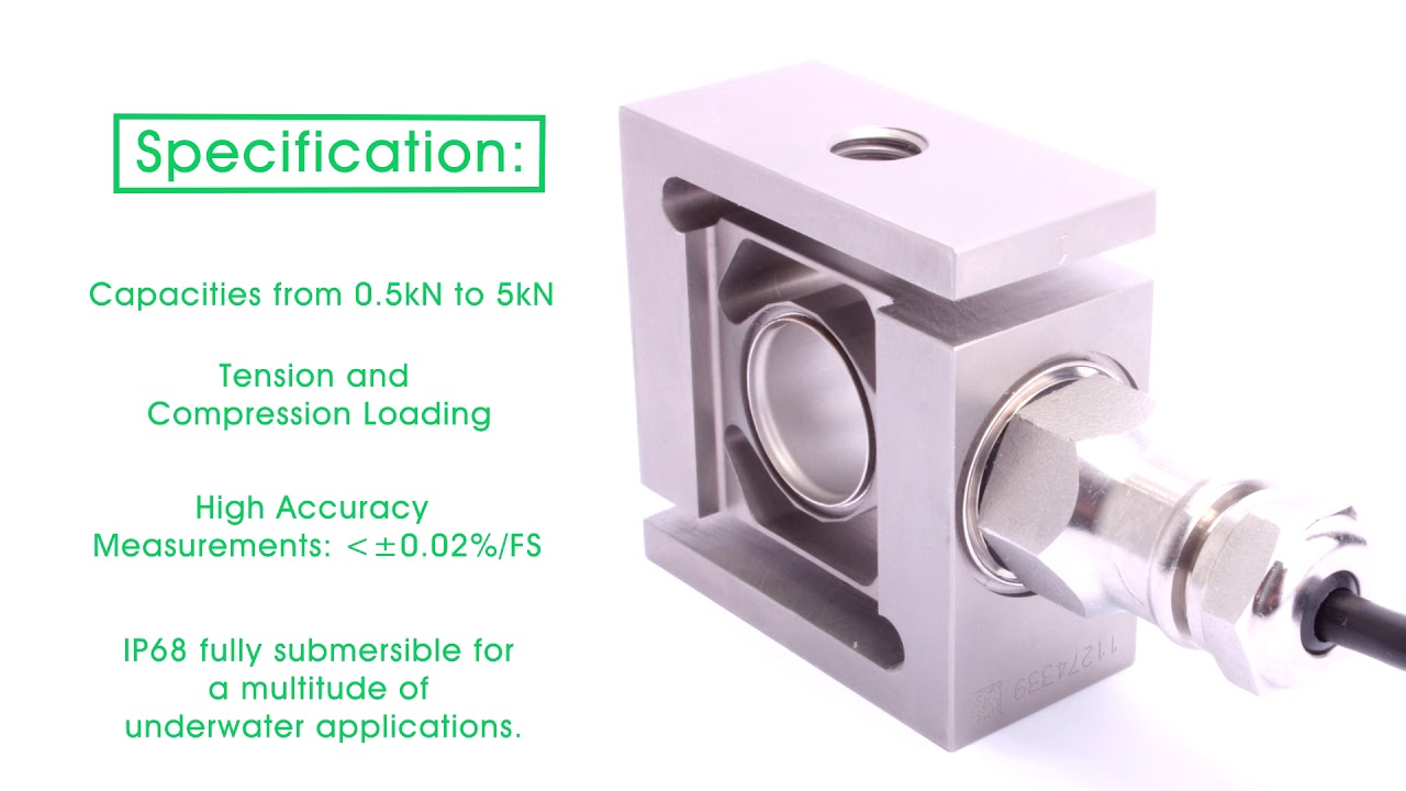
Hermetically sealed and designed for permanent long-term submersion to 10m/1bar. Find out more https://appmeas.co.uk/products/load-cells-force-sensors/submersible-s-beam-load-cell-dbbsub/
Capacities: 0-0.5kN up to 0-5kN.
@Applied Measurements’ Videos #loadcell
submersible load cell 주제에 대한 자세한 내용은 여기를 참조하세요.
S337-02 Submersible load cells – Matest
Submersible load cells testing equipment Soil. Product specification on our website. Request information with no obligation.
Source: www.matest.com
Date Published: 3/5/2022
View: 658
주제와 관련된 이미지 submersible load cell
주제와 관련된 더 많은 사진을 참조하십시오 DBBSUB Permanently Submersible Load Cell Applied Measurements #loadcell #sbeamloadcell #AppMeas. 댓글에서 더 많은 관련 이미지를 보거나 필요한 경우 더 많은 관련 기사를 볼 수 있습니다.
주제에 대한 기사 평가 submersible load cell
- Author: Applied Measurements’ Videos
- Views: 조회수 392회
- Likes: 좋아요 2개
- Date Published: 2017. 11. 2.
- Video Url link: https://www.youtube.com/watch?v=87icp9SnU-M
Are load cells waterproof?
S-Beam Load Cell in FUTEK’s Load Cell Series. This waterproof force sensor is capable of servicing numerous applications industry wide where protection from liquids is required. This product offers a perfect mixture of size, accuracy and the assurance of an overload protection.
What are the types of load cell?
When classified by the direction of load detection, load cells can be divided into the following types: tension, compression, alternating, and bending. Based on precision, load cells can be classified as ultra precision, precision, standard, and general-purpose.
Which load cell is best?
In an industrial setting, a strain gage load cell is one of the best options, because the accuracy is near perfect in applications that involve experimental stress. Sanitation and safety. In applications that demand precise mechanical balance, pneumatic load cells are the more preferable option.
How does a load cells work?
A load cell is a force transducer. It converts a force such as tension, compression, pressure, or torque into an electrical signal that can be measured and standardized. As the force applied to the load cell increases, the electrical signal changes proportionally.
How is load cell capacity calculated?
(5 v excitation X 2 Mv/v X 50 lbs, or 5 X 2 X 50 = 500. So assuming you have a 2 Mv/v and have verified you have 5 v excitation, the capacity of your load cell is 500 lbs. In other words: 2 mV/V times 5 dc excitation/sense = 10 Mv full scale.
What are the advantages of load cell?
Load cells are used for quick and precise measurements. Compared with other sensors, load cells are relatively more affordable and have a longer life span.
What are the applications of load cells?
Applications include truck scales, railway scales, supermarket scales, bench scales, heavy duty scales or any type of standard scale. Applications include machinery for bag filling, bottle filing, high speed checkweighers, multi-head packing machines, silo/tank weighing systems and conveyor scales.
How do I select a load cell?
- Understand Your Application. Look for a load cell based on the application in question. …
- Look Into Your Capacity Requirements. …
- Size and Specification Requirements. …
- Load Cell Types. …
- Load Cell Shapes. …
- Consider the Operating Environment.
What is load cell capacity?
Load cell capacity = (live weight + dead weight) / # of load cells. PLATFORM FLOOR SCALE. Scale capacity = (live weight + dead weight) * 2. Hardy standard load cell capacities will then dictate which load cells should be used.
How many load cells do I need?
Generally, you should not use any more than eight load cells. It be comes proportionally more difficult to get even weight distribution, and therefore better accuracy, on vessels with more than four load cells.
How do load cells fail?
Load cells might be damaged because of (shock) overloading, lightning strikes or heavy electrical surges in general, chemical or moisture ingress, mishandling (dropping, lifting on cable, etc.), vibration or internal component malfunction.
Which sensor is used in load cell?
A Force Sensor is defined as a transducer that converts an input mechanical load, weight, tension, compression or pressure into an electrical output signal (load cell definition). Force Sensors are also commonly known as Force Transducer.
What is column type load cell?
Column Load Cells (also known as Canister Load Cell) offers compact design for high capacity compression applications such as CNC Machine Vise Clamping Force Test. These models offer robust construction with a capacity ranging from 2,000 to 30,000 lbs.
Which type of load cell is used in weighing machine?
Shear Beam Load Cells (S-Beam Load Cell)
Have a straight block of material fixed on one end and loaded material on the other. Beam load cells, known as bending load cells, are used for industrial weighing, including industrial floor scales and tank, silo, and on-board vehicle weighing.
What is capacitive load cell?
A capacitive load cell uses a series of capacitors to measure weight across the load cell. Inside each capacitor are two charged metal plates with a dielectric, uncharged material between them. This simple construction allows the capacitor to measure weight.
Submersible Force Sensors
CAPACITY & TRACEABILITY
Capacities vary from 1 lb to 3,000,000 lbs. All units are calibrated in the laboratory using NIST traceable standards. Calibration certificates are provided with each unit.
DESIGN AND DELIVERY
The design of Sensing Systems underwater load cells allows them to be incorporated into any shape or configuration. The most common shapes are tension links and flat load cells. The outside geometry may be machined to square, rectangular, circular, or any other section or shape required by the application. Sensing Systems’ approach is to incorporate our standard sensing elements into a shape that fits the customer’s application. This allows us to deliver underwater load cells matched to the customer’s application within a short period of time. The sensing elements in our underwater load cells include design features to properly encapsulate and waterproof the electronics from the harsh environment.
ENVIRONMENT
In addition to the underwater environment and high external hydrostatic pressure, our load cells can operate throughout a wide temperature range and can be exposed to corrosive environments. The range of temperatures is -452˚F to 450˚F (-269˚C to 230˚C). Service in chemically active and magnetic environments is also possible. A large amount of our small size / low capacity underwater load cells are used for testing medical devices in saline environments set to simulate the temperature of the human body (98.6˚F). These load cells are designed to undergo billions of load cycles.
APPLICATIONS
Underwater load cells are used in a wide variety of applications and industries. Examples of applications include monitoring mooring loads for research buoys, monitoring dynamic loads on drill strings, testing medical devices in saline solutions, and determining hydrodynamic loads in underwater cages used for fish farming. Read More about Applications.
In-Line Submersible Load Cell
At a Glance
Capacities: 0-50N up to 0-50kN
Output: 0.75mV/V to 2mV/V
Fully Submersible: IP68 to 10m
Accuracy: <±0.15%/RC (0.05% typical) Optional Integral Amplifier Ideal for any Freshwater Application Fully Submersible Long-Term Immersion Protected Underwater Protection Guaranteed Thanks to ‘O’ Ring Sealing Greater Underwater Depth Ratings Available for Deep Sea Applications Special Versions Alternative Construction Materials for Seawater and other Corrosive or Aggressive Media. Description Applied Measurements high accuracy DDEN in-line submersible load cell can be used in both tension and compression and is specially designed for applications where load or force needs to be measured underwater, or in areas subject to high humidity or the risk of flooding. The submersible in-line load cell is sealed using ‘O’ rings to provide integrity at depths up to 10 metres as standard, with greater depths possible if the appropriate modifications are made to the design. Applied Measurements standard in-line waterproof load cell model DDEN, is currently being used in various applications including wave tank measurement systems and mooring buoy cable tension monitoring. Applied Measurements DDENA in-line submersible load cell is fitted with an ICA Series Load Cell Amplifier to provide a high-level analogue output, commonly 0-5Vdc, 0-10Vdc, ±10Vdc or 4-20mA, which is suitable for use with most data acquisition and control systems. An RS485 digital output is also possible by fitting the DCell Load Cell Digitiser in place of the ICA. Customised versions of our DDEN submersible load cell can be designed to meet your specific requirements. Please contact Applied Measurements expert and friendly technical team using the form in the sidebar, or by phone on +44 (0) 1189 817339, we will be happy to help discuss your requirements. Technical Specifications Rated Capacity (RC) N 0-50, 0-100, 0-250, 0-500, 0-1000, 0-2000, 0-5000, 0-10,000, 0-20,000, 0-50,000 Operating Modes Tension/Compression / Tension & Compression Sensitivity (RO) mV/V (nominal) 50N = 0.5 / 100N=1.0 / 250N = 0.75 / 500N = 1.5 / 1000N up = 2.0 Zero Balance/Offset ±%/Rated Output <1.0 Output Symmetry (tension vs. compression) ±%/Rated Output <0.25 typical Non-Linearity ±%/Rated Output <0.15 (0.05 typical) Hysteresis %/Rated Output <0.15 (0.05 typical) Repeatability ±%/Rated Output <0.1 Temperature Effect on Zero ±%/Rated Output/ ˚C <0.005 Temperature Effect on Sensitivity ±%/Applied Load/ ˚C <0.005 Input Resistance Ohms 700 Output Resistance Ohms 700 Insulation Resistance Megohms >5000 @ 50Vdc Excitation Voltage Volts AC or DC 10 recommended (2-15 acceptable) – Note mV/V only, see page 5 for details of conditioned output versions. Operating Temperature Range ˚C -20 to +80 Compensated Temperature Range ˚C 0 to +70 Storage Temperature Range ˚C -20 to +80 Safe Overload % of Rated Capacity 150 Ultimate Overload % of Rated Capacity 200 Deflection @ Rated Capacity mm 50N=0.08; 100N=0.12; 250N=0.09; 500N=0.06; 1000N=0.04; 2000N=0.03; 5000N=0.02; 10,000N=0.015; 20,000N=0.01; 50,000N=0.03 Fundamental Resonant Frequency* kHz 50N=1.7; 100N=1.3; 250N=0.72; 500N=1.18; 1000N=2; 2000N=3.1; 5000N=6.1; 10,000N=9.9; 20,000N=18.2; 50,000N=13.3 IP Rating (Environmental Protection) IP68 to 10m depth (please consult sales for greater depths) Weight (excluding cable) kg 50N to 20kN: 0.3kg / 50kN: 0.45kg, Fatigue Life 108 cycles typical (109 cycles on fatigue-rated version) Cable Length (as standard) metres 2 Cable Type 4-core screened submersible, PUR (weight: 82g/m) sheath, Ø7.5 Construction Materials / Wetted Parts 17-4PH Stainless Steel, 303 Stainless Steel, PUR, TPE, Silicone Resolution 1 part in 250,000 (with appropriate instrumentation) Pressure Effect on Output 9N/mH²O nominal *The resonant frequency is calculated with the body of the load cell attached to a large plate, ensuring that only the sensing element oscillates: This is vital to achieve the highest natural frequency and subsequent frequency response.
Product Dimensions
All dimensions are in mm
Model Capacity A B C ØD E DDEN 0-50N up to 0-20kN 67 15 35 44 M12x1.75 DDEN 0-50kN 71 18 35 44 M16x2.0 DDENA 0-50N up to 0-20kN 67 15 35 44 M12x1.75 DDENA 0-50kN 71 17 37 50 M16x2.0
Wiring Details
Wire mV/V Output 3-Wire Voltage or Current Otput 4-Wire Voltage Output 2-Wire Current RS485 Digital Red +ve excitation +ve supply +ve supply +ve supply +5.4 to +18Vdc supply Blue -ve excitation 0V common -ve supply -ve supply / signal -ve supply White +ve signal (tension) * +ve signal +ve signal N/C RS485 (B) Data -ve Yellow -ve signal N/C -ve signal N/C RS485 (A) Data +ve Screen To ground – not connected to load cell body * +ve signal in tension is standard, +ve signal in compression can also be offered.
Ordering Codes & Options
Core Product Capacity (inc Engineering Units) Cable Length (m) Specials Code Example Result DDEN 50N 002 000 DDEN-50N-002-000 DDEN 100N 002 000 DDEN-100N-002-000 DDEN 250N 002 000 DDEN-250N-002-000 DDEN 500N 002 000 DDEN-500N-002-000 DDEN 1000N 002 000 DDEN-1000N-002-000 DDEN 2000N 002 000 DDEN-2000N-002-000 DDEN 5000N 002 000 DDEN-5000N-002-000 DDEN 10kN 002 000 DDEN-10kN-002-000 DDEN 20kN 002 000 DDEN-20kN-002-000 DDEN 50kN 002 000 DDEN-50kN-002-000
Mounting And Installation Accessories
Rod End Bearings for Tension Use
Designed to align forces through the principle axis of the load cell thus reducing the effects of extraneous forces, hence offering improved performance from the cell.
Rod End Bearings are used where tensile forces are being applied.
Maintenance-free rod ends are a complete units made up of a housing with both an integral shank (with an internal or external thread) and a maintenance-free spherical plain bearing, located within the housing.
Key Features:
Supports radial loads in a tensile or compressive direction.
Suitable for unilateral loads – can support alternating loads and alternating loads in combination with bearing GE..UK-2RS, consult sales.
Stainless Steel for corrosion resistance.
Are maintenance-free.
Fitted with radial spherical plain bearings.
PTFE composite sliding contact surfaces.
Enables compact adjacent construction thanks to its thin-walled design of the eye housing.
All dimensions are in mm
LOAD CELL ORDERING CODES Size (D) B M A F L K J O SW G GL Static load C 0 kN Dynamic load C kN Limiting Speed rev/min Weight g DDEN + DDENA-50N to 20kN GIRSW-12RR-316 12 16 12 32 50 66 22 17.5 15.4 19 M12 22 34.5 32 300 115 DDEN-50kN GIRSW-16RR-316 16 21 15 42 64 85 27 22 19.3 22 M16 28 60.5 52.5 230 230
Downloads CAD Model Files Our 3D models are provided in STEP format and can be viewed using FreeCAD. Other formats can be provided on request. The .zip file below contains a separate model for each product variant. DDEN DDENA STEP
Case Studies Submersible Load Cells Lower the Cost of Large Tidal Turbine Designs This case study aims to significantly reduce the cost of large scale tidal turbine designs using our submersible load cells. The tidal turbine test rig was placed in a state-of-the-art test tank, where the team were able to increasing the size, flow rate and turbulence levels within the tank. Lowering the cost of rotor blade manufacture would make this renewable energy more economical to use and widely accessible, benefiting not only the UK renewable tidal energy markets but developing tidal energy countries too. Our submersible load cells measured both the torque and the thrust of the underwater tidal turbine design.
Read more…
Interested in this product? Send us an enquiry… Please leave this field empty. I agree to the privacy and cookies policy Δ
Why Applied Measurements?
Waterproof Submersible Load Cell
The LSB210 is a Submersible Jr. S-Beam Load Cell in FUTEK’s Load Cell Series. This waterproof force sensor is capable of servicing numerous applications industry wide where protection from liquids is required. This product offers a perfect mixture of size, accuracy and the assurance of an overload protection. The LSB210 waterproof Load Cell is available in 100g to 100lbs (1N – 445N) capacities.
With all of its design features this Miniature S Beam Submersible Load Cell has a high accuracy with a thickness of 0.25 inches and profile height of 0.75 inches it is suitable for critical applications involving tight or limited space. This Jr. S Beam Load Cell can be modified or customized to meet your requirements and most capacities are in our inventory making them available for 24 hour shipping.
How to Select the Right Load Cell
The process of choosing a load cell is often complicated by the fact that each option has its own unique benefits. Truth be told, different load cell applications have their own special requirements. As such, you should discuss load cell capacity requirements with a knowledgeable supplier in advance of making a selection.
The decision you arrive at based on the load cell selection criteria is only one step in the overall process of implementation. Beyond that, you must still ensure you correctly installed and equipped the load cell with the proper instrumentation, otherwise you will not get precise measurements. This load cell selection guide will help you make a more informed choice.
Understand Your Application
In order to understand your load cell application, you must determine how to conduct the measurement and how the load should be applied. The process of measurement concerns a variety of factors, including:
Bending
Compression
Multi-axis
Tension
Load cell measurements help determine the weight of tanks and the performance of durability and break point tests.
Define Your Capacity Requirements
Determine the maximum amount of load capacity required for your applications, as well as the necessary minimum.
As you go about determining the load cell capacity requirements of your application, you will need to bear in mind the extraneous factors. To ensure you have the optimal capacity, choose one that exceeds the highest operating load. Moreover, you will need to establish which engineering units will be required for the process. The combined stress caused by extraneous load and moments can put a dampener on the performance of an application.
Consequently, you could seriously compromise the accuracy of an application if you fail to select the proper load cell.
The majority of in-line sensors are ill-equipped for the possibility of extraneous load. For the more high-endurance applications, choose a sensor with an optimal fatigue rating, as specified by the manufacturer.
Define Your Load Cell Needs
In order to select the right load cell, determine the needs of your applications. The following questions can help you make that determination:
Is the load of your application dynamic or static?
Do you intend to make in-line use of the load cell?
Do you intend to make side-mounted use of the load cell?
Another factor is the design of the device in question. Load cell capacity requirements are in part determined by the shape of the device in use, which could include:
Compressor washer
Female/male thread
Flange mount
In-line
Side mount
Thru-hole
When choosing a load cell, make sure you first take these factors into account to ensure that your purchase fits the requirements of the applications.
Define Your Size and Specification Requirements
Another key component of load cell selection criteria is the definition of size requirements. Most specifically, you must determine the needs of your application along the following measures:
Width and height
Weight
Length
To ensure you have sufficient load cell capacity, you will also need to determine the possible variances that could arise, such as:
Bridge resistance
Hysteresis
Nonlinearity
Finally, you will need to base your choice in part on whether you will conduct the applications in hot or cold temperatures. Likewise, load cell capacity requirements can be determined by whether applications are carried out in submerged settings or out of water. Factors such as the frequency of response and the possible need for special calibration are also matters of interest when you determine your requirements.
Select Instrumentation
At the same time you choose a load cell, be prepared to also select any necessary instruments for the applications you intend to perform. When you pick all the vital pieces at the same time, you can better ensure a system-wide functionality between every component in use.
You should also include system calibration in your order. This will ensure you integrate your instrument and sensor for the same system. Calibration is a vital component to all load cell applications.
Load Cell Applications
A variety
of load cell options are preferable in relation to the demands of the setting or application in question. As you learn how to select the right load cell for a particular application, consider your foremost requirements. In general, the performance of a load cell will correlate to the demands of an application as follows:
High endurance . In an industrial setting, a strain gage load cell is one of the best options, because the accuracy is near perfect in applications that involve experimental stress.
. In an industrial setting, a strain gage load cell is one of the best options, because the accuracy is near perfect in applications that involve experimental stress. Sanitation and safety . In applications that demand precise mechanical balance, pneumatic load cells are the more preferable option.
. In applications that demand precise mechanical balance, pneumatic load cells are the more preferable option. Remote applicability. When an application is conducted in a remote setting, the best choice is a hydraulic load cell, which can operate without a power connection.
Load cell selection criteria — or the choice between a strain gage, pneumatic or hydraulic load cell — should largely be determined by the preceding factors.
Load Cell Types
Strain Gauge Load Cells
The most widely used load cells throughout the industrial sector are of the strain gauge variety. People value strain gauge load cells for their durability, stiffness and resonance values. The stain gauge of the load cell is a planar resistor that deforms in connection to the activities of the load cell material. The electrical resistance of the strain gauge changes in form at levels that correlate to the strain.
Piezoelectric Load Cells
With the piezoelectric load cell, the deformation is similar to that of the strain gauge load cell. However, the piezoelectric matter generates voltage in response to the changing form of the load cell. The voltage does not serve as a measurement of static values, but nonetheless remains important when the strain undergoes changes. With the conditioning of a charge amplifier, the piezoelectric load cell measures wide ranges particularly well.
Hydraulic Load Cells
The hydraulic load cell works in combination with a cylinder and diaphragm-covered piston. It works like this — place oil in the load cell, and intensify the pressure of the oil by movement the piston makes in response to the load. The transfer of pressure through a hose gauges hydraulic pressure. Due to the lack of electrical parts, a hydraulic load cell can safely be used in hazardous environments.
Pneumatic Load Cells
The pneumatic load cell is made to control the balance of pressure. One side of the diaphragm is exposed to the pressure of air, which travels through the under-nozzle of the load cell. An attached gauge measures the pressure in the load cell.
Load Cell Shapes
S-Beam Load Cells
You can identify S-Beam load cells — alternately known as Z-Beam load cells —by their shape, which resembles the namesake letter. Used primarily in applications that involve tension, S-Beam load cells provide accuracy when the weighing system becomes suspended or hung.
In addition to their high precision, S-Beam load cells enjoy popularity due in large part their affordability and ease of setup. However, S-Beam load cells are made exclusively for in-line applications and tend not to perform accurately with extraneous loads.
Beam Load Cells
You can use beam load cells, named after their rectangular shape, for everything from static weight and dynamic weighing to hopper weighing, silo weighing and tank weighing. Representing a broad category, beam load cells can be subdivided as follows:
Bending beam . Designed for bench scale applications, bending beams need to be set up with utmost precaution, otherwise side-loading could occur. Constructed from aluminum alloy, bending beams are ideal for low-capacity operations in the range of 1 to 500 kg.
. Designed for bench scale applications, bending beams need to be set up with utmost precaution, otherwise side-loading could occur. Constructed from aluminum alloy, bending beams are ideal for low-capacity operations in the range of 1 to 500 kg. Shear beam. Designed with an interior shear machine — which keeps the cell safeguarded from side-loading — shear beams come in single-ended and double-ended varieties. Medium-capacity applications generally employ the single, while applications that call for higher capacity use the double. Made of carbon-steel alloy with nickel plating, shear beams are resistant to corrosion and optimal for heavy-duty applications.
Overall, bending beam and shear beam load cells are a low-cost option for a range of industrial applications.
Canister Load Cells
Named for their canister-like shape, canister load cells date back to the very beginning of the strain gauge load cell. In contemporary use, canister load cells have become a common choice for compression applications with capacity requirements of 100,000 lbs. or more.
Pancake Load Cells
Applications that involve high precision use the pancake load cell, alternately known as the Low Profile load cell. Pancake load cells come in one of two designs — those with bending beams and those with shear struts. The majority of pancake load cells feature a mounting rig and female center-thread, which makes them suitable for compression and tension applications.
Button Load Cells
As one of the smaller load cell designs, button load cells received their name from their raised center-button. Due to their compactness, button load cells are one of the most ideal options for applications in narrow, confined settings. Button load cells are especially popular in the medical sector, where operating spaces come at a premium. Applications in the automation industry also benefit from the small design of button load cells.
Thru-Hole Load Cells
Alternately known as donut load cells due to their Lifesaver-like shape, thru-hole load cells make an ideal choice for applications that involve the use of clamp force or employ the measurement of bolt force. Designed for high stiffness, thru-hole load cells provide utmost accuracy in press-load and off-center applications.
Adverse Loading Conditions
Consider the following when dealing with adverse loading conditions:
Overloading capacity. This must be determined first in order to know the level at which the load cell must be proof loaded, otherwise the risk factors could be too high.
This must be determined first in order to know the level at which the load cell must be proof loaded, otherwise the risk factors could be too high. Dynamic loads. A load cell rating must take into account the persistence, speed and pressure of the dynamic loads, otherwise you might fail to determine the overload capacity and leave the load cell vulnerable in the event of high dynamics.
A load cell rating must take into account the persistence, speed and pressure of the dynamic loads, otherwise you might fail to determine the overload capacity and leave the load cell vulnerable in the event of high dynamics. Fatigue loading. You must determine the per-cycle load level along with information about cycle frequency and totals throughout the life of a load cell. Otherwise, the succession of cycles endured by the load cell could result in fatigue loading.
You must determine the per-cycle load level along with information about cycle frequency and totals throughout the life of a load cell. Otherwise, the succession of cycles endured by the load cell could result in fatigue loading. Off-axis loading. The accuracy and well being of a load cell can be compromised by off-axis loading, which can occur in applications where the load does not conform to the design axis. You can counter the problem with the use of bearings and load buttons, while some load cells resist the problem entirely.
Contact Group Four Today for Your Load Cell Needs
Group Four is a leading supplier of load cells used for applications that involve air and liquid pressure monitoring, compression testing, data acquisition, insertion forces, overload monitoring, peel force measurement, process control, tensile testing, torque measurement and a whole lot more.
At Group Four Transducers, we offer equipment for use in the manufacturing sector for the purposes of safety and quality control. Many organizations use our sensors in applications to take measurements on the pressure that results from physical processes.
For example, a construction company could monitor the amount of pressure that goes into effect during a mechanical lifting operation with one of our sensors, to ensure the crane bearing the weight does not become overloaded. Meanwhile, makers of food products accurately weigh ingredients and ensure the proper balance of additives with our sensors.
At Group Four Transducers, we provide the best customer service in our industry on our full range of items, which include products from competing companies in addition to our own product line. By contrast, most manufacturers only carry their own line, and this forces many customers to go to multiple sources to purchase all the necessary components for a load cell system.
With Group Four Transducers, you can buy everything you need in one purchase. Remember, the best way to choose a load cell is to determine all the necessary components at once so you can buy them at the same time from the same source, as this will ensure compatibility between all the parts to your system.
The capacity of our load cells ranges from 0-10 grams to 0-3 million lbs. Companies around the world use our load cells, including those in the automotive, aerospace, construction, education, energy, manufacturing and medical sectors, in addition to a range of other industries.
Contact Group Four Transducers today for more information on the best load cell for your application or to request a quote. We can find what you are looking for and offer custom solutions that will meet your needs.
Load cell
Type of force transducer
A load cell is a force transducer. It converts a force such as tension, compression, pressure, or torque into an electrical signal that can be measured and standardized. As the force applied to the load cell increases, the electrical signal changes proportionally. The most common types of load cell used are strain gauges, pneumatic, and hydraulic.
Strain gauge load cell [ edit ]
Strain gauge load cells are the kind most often found in industrial settings. It is ideal as it is highly accurate, versatile, and cost-effective. Structurally, a load cell has a metal body to which strain gauges have been secured. The body is usually made of aluminum, alloy steel, or stainless steel which makes it very sturdy but also minimally elastic. This elasticity gives rise to the term “spring element”, referring to the body of the load cell. When force is exerted on the load cell, the spring element is slightly deformed, and unless overloaded, always returns to its original shape. As the spring element deforms, the strain gauges also change shape. The resulting alteration to the resistance in the strain gauges can be measured as voltage. The change in voltage is proportional to the amount of force applied to the cell, thus the amount of force can be calculated from the load cell’s output.
Strain Gauges [ edit ]
A strain gauge is constructed of very fine wire, or foil, set up in a grid pattern and attached to a flexible backing. When the shape of the strain gauge is altered, a change in its electrical resistance occurs. The wire or foil in the strain gauge is arranged in a way that, when force is applied in one direction, a linear change in resistance results. Tension force stretches a strain gauge, causing it to get thinner and longer, resulting in an increase in resistance. Compression force does the opposite. The strain gauge compresses, becomes thicker and shorter, and resistance decreases. The strain gauge is attached to a flexible backing enabling it to be easily applied to a load cell, mirroring the minute changes to be measured.
Since the change in resistance measured by a single strain gauge is extremely small, it is difficult to accurately measure changes. Increasing the number of strain gauges applied collectively magnifies these small changes into something more measurable. A set of 4 strain gauges set in a specific circuit is an application of a Wheatstone bridge.
Wheatstone Bridge [ edit ]
A Wheatstone bridge is a configuration of four balanced resistors with a known excitation voltage applied as shown below:
Excitation voltage V EX {\displaystyle V_{\text{EX}}} is a known constant and output voltage V o {\textstyle V_{o}} is variable depending on the shape of the strain gauges. If all resistors are balanced, meaning R 1 R 2 = R 4 R 3 {\displaystyle {\frac {R1}{R2}}={\frac {R4}{R3}}} then V o {\textstyle V_{o}} is zero. If the resistance in even one of the resistors changes, then V 0 {\displaystyle V_{0}} will likewise change. The change in V o {\textstyle V_{o}} can be measured and interpreted using Ohm’s law. Ohm’s law states that the current ( I {\textstyle I} , measured in amperes) running through a conductor between two points is directly proportional to the voltage V {\textstyle V} across the two points. Resistance ( R {\displaystyle R} , measured in ohms) is introduced as the constant in this relationship, independent of the current. Ohm’s law is expressed in the equation I = V / R {\displaystyle I=V/R} .
When applied to the 4 legs of the Wheatstone bridge circuit, the resulting equation is:
V o = ( R 3 R 3 + R 4 − R 2 R 1 + R 2 ) V EX {\displaystyle V_{o}=\left({\frac {R3}{R3+R4}}-{\frac {R2}{R1+R2}}\right)V_{\text{EX}}}
In a load cell, the resistors are replaced with strain gauges and arranged in alternating tension and compression formation. When force is exerted on the load cell, the structure and resistance of the strain gauges changes and V o {\textstyle V_{o}} is measured. From the resulting data, V o {\textstyle V_{o}} can be easily determined using the equation above.[1]
Common types of load cells [ edit ]
There are several types of strain gauge load cells:[2]
Single Point load cells; used in small to medium platform scales with platform sizes of 200x200mm up to 1200×1200 mm.
Planar Beam load cells; used in low profile solutions where space is limited, like medical scales and retail scales.
Bending Beam load cells; used in pallet, platform and small hopper scales.
Shear Beam load cells; used in low profile scale and process applications, available in capacities from 100kg up to 50t.
Dual Shear Beam load cells; used in truck scales, tank and hopper applications.
S-type load cells; used in tension applications where you will find static and dynamic loads.
Compression load cells; used in truck scales, large platform scales, weighbridges and hopper scales.
Ring Torsion load cells; used in high accuracy hoppers, silo’s, platforms and pallet scales.
Spoke Type load cells; used in low profile, high precision application. High forces varying from 1t-500t.
Onboard load cells; used for onboard weighing systems on trucks, tractors and other vehicles.
Loadpins; used in applications for measuring dynamic, static or hoisting forces.
Weighpads; portable weighpads for the weighing of cars and the measure the center of gravity of planes.
Specials; all kind of special sensors.
Pneumatic load cell [ edit ]
The pneumatic load cell is designed to automatically regulate the balancing pressure. Air pressure is applied to one end of the diaphragm and it escapes through the nozzle placed at the bottom of the load cell. A pressure gauge is attached to the load cell to measure the pressure inside the cell. The deflection of the diaphragm affects the airflow through the nozzle as well as the pressure inside the chamber.
Hydraulic load cell [ edit ]
The hydraulic load cell uses a conventional piston and cylinder arrangement with the piston placed in a thin elastic diaphragm. The piston doesn’t actually come in contact with the load cell. Mechanical stops are placed to prevent over strain of the diaphragm when the loads exceed certain limit. The load cell is completely filled with oil. When the load is applied on the piston, the movement of the piston and the diaphragm results in an increase of oil pressure. This pressure is then transmitted to a hydraulic pressure gauge via a high pressure hose.[3] The gauge’s Bourdon tube senses the pressure and registers it on the dial. Because this sensor has no electrical components, it is ideal for use in hazardous areas.[4] Typical hydraulic load cell applications include tank, bin, and hopper weighing.[5] By example, a hydraulic load cell is immune to transient voltages (lightning) so these type of load cells might be a more effective device in outdoor environments. This technology is more expensive than other types of load cells. It is a more costly technology and thus cannot effectively compete on a cost of purchase basis.[6]
Other types [ edit ]
Vibrating load cell [ edit ]
Vibrating wire load cells, which are useful in geomechanical applications due to low amounts of drift, and capacitive load cells where the capacitance of a capacitor changes as the load presses the two plates of a capacitor closer together.
Piezoelectric load cell [ edit ]
Piezoelectric load cells work on the same principle of deformation as the strain gauge load cells, but a voltage output is generated by the basic piezoelectric material – proportional to the deformation of load cell. Useful for dynamic/frequent measurements of force. Most applications for piezo-based load cells are in the dynamic loading conditions, where strain gauge load cells can fail with high dynamic loading cycles. The piezoelectric effect is dynamic, that is, the electrical output of a gauge is an impulse function and is not static. The voltage output is only useful when the strain is changing and does not measure static values.
However, depending on conditioning system used, “quasi static” operation can be done. Using a charge amplifier with a long time constant allows accurate measurement lasting many minutes for small loads up to many hours for large loads. Another advantage of Piezoelectric load cells conditioned with a charge amplifier is the wide measuring range that can be achieved. Users can choose a load cell with a range of hundred of kilonewtons and use it for measuring few newtons of force with the same signal-to-noise ratio; again this is possible only with the use of a charge amplifier for conditioning.
Common issues [ edit ]
Mechanical mounting: the cells have to be properly mounted. All the load force has to go through the part of the load cell where its deformation is sensed. Friction may induce offset or hysteresis. Wrong mounting may result in the cell reporting forces along undesired axis, which still may somewhat correlate to the sensed load, confusing the technician.
Overload: Within its rating, the load cell deforms elastically and returns to its shape after being unloaded. If subjected to loads above its maximum rating, the material of the load cell may plastically deform; this may result in a signal offset, loss of linearity, difficulty with or impossibility of calibration, or even mechanical damage to the sensing element (e.g. delamination, rupture).
Wiring issues: the wires to the cell may develop high resistance, e.g. due to corrosion. Alternatively, parallel current paths can be formed by ingress of moisture. In both cases the signal develops offset (unless all wires are affected equally) and accuracy is lost.
Electrical damage: the load cells can be damaged by induced or conducted current. Lightning hitting the construction, or arc welding performed near the cells, [7] can overstress the fine resistors of the strain gauges and cause their damage or destruction. For welding nearby, it is suggested to disconnect the load cell and short all its pins to the ground, nearby the cell itself. High voltages can break through the insulation between the substrate and the strain gauges.
can overstress the fine resistors of the strain gauges and cause their damage or destruction. For welding nearby, it is suggested to disconnect the load cell and short all its pins to the ground, nearby the cell itself. High voltages can break through the insulation between the substrate and the strain gauges. Nonlinearity: at the low end of their scale, the load cells tend to be nonlinear. This becomes important for cells sensing very large ranges, or with large surplus of load capability to withstand temporary overloads or shocks (e.g. the rope clamps). More points may be needed for the calibration curve.
Particularity of application: A load cell that is not well suited to the specific magnitude and type of pressure will have poor accuracy, resolution, and reliability.
Excitation and rated output [ edit ]
The bridge is excited with stabilized voltage (usually 10V, but can be 20V, 5V, or less for battery powered instrumentation). The difference voltage proportional to the load then appears on the signal outputs. The cell output is rated in millivolts per volt (mV/V) of the difference voltage at full rated mechanical load. So a 2.96 mV/V load cell will provide 29.6 millivolt signal at full load when excited with 10 volts.
Typical sensitivity values are 1 to 3 mV/V. Typical maximum excitation voltage is around 15 volts.
Wiring [ edit ]
The full-bridge cells come typically in four-wire configuration. The wires to the top and bottom end of the bridge are the excitation (often labelled E+ and E−, or Ex+ and Ex−), the wires to its sides are the signal (labelled S+ and S−). Ideally, the voltage difference between S+ and S− is zero under zero load, and grows proportionally to the load cell’s mechanical load.
Sometimes a six-wire configuration is used. The two additional wires are “sense” (Sen+ and Sen−), and are connected to the bridge with the Ex+ and Ex- wires, in a fashion similar to four-terminal sensing. With these additional signals, the controller can compensate for the change in wire resistance due to external factors, e.g. temperature fluctuations.
The individual resistors on the bridge usually have resistance of 350 Ω. Sometimes other values (typically 120 Ω, 1,000 Ω) can be encountered.
The bridge is typically electrically insulated from the substrate. The sensing elements are in close proximity and in good mutual thermal contact, to avoid differential signals caused by temperature differences.
Using multiple cells [ edit ]
One or more load cells can be used for sensing a single load.
If the force can be concentrated to a single point (small scale sensing, ropes, tensile loads, point loads), a single cell can be used. For long beams, two cells at the end are used. Vertical cylinders can be measured at three points, rectangular objects usually require four sensors. More sensors are used for large containers or platforms, or very high loads.
If the loads are guaranteed to be symmetrical, some of the load cells can be substituted with pivots. This saves the cost of the load cell but can significantly decrease accuracy.
Load cells can be connected in parallel; in that case, all the corresponding signals are connected together (Ex+ to Ex+, S+ to S+, …), and the resulting signal is the average of the signals from all the sensing elements. This is often used in e.g. personal scales, or other multipoint weight sensors.
The most common color assignment is red for Ex+, black for Ex−, green for S+, and white for S−.
Less common assignments are red for Ex+, white for Ex−, green for S+, and blue for S−, or red for Ex+, blue for Ex−, green for S+, and yellow for S−.[8] Other values are also possible, e.g. red for Ex+, green for Ex−, yellow for S+ and blue for S−.[9]
Ringing [ edit ]
Every load cell is subject to “ringing” when subjected to abrupt load changes. This stems from the spring-like behavior of load cells. In order to measure the loads, they have to deform. As such, a load cell of finite stiffness must have spring-like behavior, exhibiting vibrations at its natural frequency. An oscillating data pattern can be the result of ringing. Ringing can be suppressed in a limited fashion by passive means. Alternatively, a control system can use an actuator to actively damp out the ringing of a load cell. This method offers better performance at a cost of significant increase in complexity.
Uses [ edit ]
Load cells are used in several types of measuring instruments such as laboratory balances, industrial scales, platform scales[10] and universal testing machines.[11] From 1993 the British Antarctic Survey installed load cells in glass fibre nests to weigh albatross chicks.[12] Load cells are used in a wide variety of items such as the seven-post shaker which is often used to set up race cars.
Load cells weighing performances [ edit ]
Load cells are commonly used to measure weight in an industrial environment. They can be installed on hoppers, reactors, etc., to control their weight capacity, which is often of critical importance for an industrial process. Some performance characteristics of the load cells must be defined and specified to make sure they will cope with the expected service. Among those design characteristics are:
Combined error
Minimum verification interval
Resolution
Load cell specifications [ edit ]
The electrical, physical, and environmental specifications of a load cell help to determine which applications it is appropriate for. Common specifications include:[13]
Full Scale Output (FSO): Electronic output expressed in mV/V. Measured at full scale.
Combined Error: percent of the full scale output that represents the maximum deviation from the straight line drawn between no load and load at rated capacity. Often measured during decreasing and increasing loads.
Non-Linearity: The maximum deviation of the calibration curve from a straight line drawn between the rated capacity and zero load. Measured on increasing load and expressed as percent of full scale output.
Hysteresis: Maximum difference between load cell output signals for the same applied load. The first measurement can be obtained by decreasing the load from rated output and the second by increasing the load from zero.
Repeatability: Maximum difference between output measurements for repeated loads under identical conditions. Measured in percent of rated output.
Zero Balance (Offset): Output reading of the load cell with rated excitation under no load. The deviation in output between a true zero measurement and a real load cell under zero load expressed as a percentage of full scale output.
Compensated Temperate Range: The temperature range over which a load cell is compensated so that it can ensure zero balance & rated output within specified limits. Expressed as °F or °C.
Operating Temperature Range: Temperature range extremes in which a load cell can operate without permanent, adverse effects on any of its performance characteristics. Expressed as °F or °C.
Temperature Effect on Output: Modification of output readings caused by load cell temperature. Expressed as percent of full scale output per degree of °F or °C.
Temperature Effect on Zero: Change in zero balance caused by ambient temperature changes. Expressed as percent of full scale output per degree of °F or °C.
Input Resistance: Input resistance of the load cell’s bridge circuit. Measured at the positive & negative excitation leads with no load applied. Measured in Ohms.
Output Resistance: Output resistance of the load cell’s bridge circuit. Measured at the positive & negative excitation leads with no load applied. Measured in Ohms.
Insulation Resistance: The resistance measured along pathways between the: bridge circuit and transducer element, bridge circuit and the cable shield, and the transducer element and the cable shield. Typically measured at fifty volts under standard test conditions.
Recommended Excitation: Maximum recommended excitation voltage of the transducer for it to operate within its specifications. Expressed in VDC.
Cable Length: Length of the standard cable for which the load cell is calibrated. Cable length affects how the load cell is calibrated.
Safe Overload: The maximum load that can be applied to a load cell without causing permanent effects to its performance specifications. Measured as a percent of full scale output.
Ultimate Overload: Maximum load that can be withstood without causing structural failure.
Material: Substance that comprises the spring element of the load cell.
Load cell calibration [ edit ]
Load cells are an integral part of most weighing systems in industrial, aerospace and automotive industries, enduring rigorous daily use. Over time, load cells will drift, age and misalign; therefore, they will need to be calibrated regularly to ensure accurate results are maintained.[14] ISO9000 and most other standards specify a maximum period of around 18 months to 2 years between re-calibration procedures, dependent on the level of load cell deterioration. Annual re-calibration is considered best practice by many load cell users for ensuring the most accurate measurements.
Standard calibration tests will use linearity and repeatability as a calibration guideline as these are both used to determine accuracy. Calibration is conducted incrementally starting working in ascending or descending order. For example, in the case of a 60 tonne load cell, then specific test weights that measure in 5, 10, 20, 40 and 60 tonne increments may be used; a five step calibration process is usually sufficient for ensuring a device is accurately calibrated. Repeating this five-step calibration procedure 2-3 times is recommended for consistent results.[15]
See also [ edit ]
References [ edit ]
Standards [ edit ]
Submersible load cells
With over 28 years of experience, we have tested and validated our load cells in the most extreme operating conditions. Their durability is due, in particular, to the special technique we use for the internal bonding of our strain gauges.
For more than half of that period, we have been manufacturing submersible load pins for use in many different situations, such as operating in fresh water, testing in a controlled environment and carrying out measurements in the deep sea (> 1,500 m depth).
Most of our load cells are available, as an option, in versions with an Ingress Protection (IP) rating of either IP66, IP67 or IP68.
IP66 means being protected against powerful water jets or heavy seas;
means being protected against powerful water jets or heavy seas; IP67 means being protected against the effects of immersion (up to 1 m depth) for a fixed time; (We have also developed an in-house ‘IP67M’ option, particularly suited to the marine environment thanks to the use of a suitable sealing material that does not need to be completely waterproof.)
means being protected against the effects of immersion (up to 1 m depth) for a fixed time; (We have also developed an in-house ‘IP67M’ option, particularly suited to the marine environment thanks to the use of a suitable sealing material that does not need to be completely waterproof.) IP68 means being protected against complete and continuous submersion in the deep sea.
Our submersible load cells are perfectly designed for a wide range of applications:
Oil and gas drilling
Underwater search
Shipbuilding
Monitoring systems
Tank testing
Working at sea
Mooring control for marine equipment used in the oil industry;
Remotely operated vehicles (ROVs) – for tension control of the umbilical cable.
We make some standard submersible models. However, as our speciality is the development of tailor-made solutions, we can include protection against water in most of our load cell designs, taking into account the:
Environment (sea water, fresh water or tap water)
Degree of protection
Temperature
Pressure.
As an option, all of our models can be supplied with an amplifier with an analogue, digital or completely specific output. For example, we have designed a custom-made submersible load pin that combines an electronic measuring instrument with a battery and a display, enclosed with a pressure-resistant glass window and a volt-free contact switch.
Submersible Load Cells – Underwater Load Cells
Underwater and Submersible Load Cells
Load Cell Central offers custom and stock submersible load cells for underwater applications, as well as a full line of supporting hardware and electronics. Suitable for use in offshore oil and gas production, towing, transport and salvage, commercial fisheries, and other marine applications, our standard underwater load cells are submersible up to 95 psi and come in capacities up to 50,000 lbs. We can also custom build a transducer to meet the unique needs of your operation. Read More
Submersible Load Cell Hardware and Accessories
You’ll also find dozens of accessories for our submersible load cells ready for use in a variety of underwater applications. We have hardware such as eye bolts, thread adaptors and rod ends to hardware linkages including electrical isolators and wire rope cable assemblies. Load Cell Central offers consultation, custom designs, calibrations, technical support, and much more for your industrial and marine weighing applications.
Custom Underwater Load Cells
If our stock submersible load cells aren’t perfect for your operation, contact us to discuss custom builds. Our UWTL series products are built to order, allowing you to specify your requirements — including connectors, capacity, dimensions, output, and cable length — for underwater load cells suitable for use at depths of up to 5,000 meters. Internal signal conditioners are also available for outputs like 4-20mA, 0-5VDC, 0-10VDC, +/-10VDC, RS232, RS485, USB, acoustic, and more!
To request a quote for custom submersible load cells or to inquire about any of our other load cell products for marine use, contact Load Cell Central today.
Submersible Load Cell
Home >> Pressure Strain and… >> Load Cells, Force Se… >> Low Profile Load Cel… >> LSHD Series Waterproof Low Profile Load Cells
Fully Submersible LSHD Series Submersible Load Cell
Click for . USD$35,805.00 LSHD-100
For Wet or Washdown Applications
High Accuracy
5-Point NIST Traceable Calibration Included
Hermetically Sealed for Wet and Submerged Applications
Submersible Load Cell
All Stainless Steel Construction for Harsh Industrial Environments
1% Interchangeability for Scale Applications
High Capability to Resist Side Loads
Low Profile for Easy Installations
3 m (10′) Waterproof Cable Standard, Longer Lengths Available
The LSHD submersible low profile load cell series are hermetically sealed and have a high pressure, high temperature molded waterproof cable seal to assure long life in wet or submerged applications such as truck scales or rail scales. They are supplied with a standard length of 3 m (10′) of cable, however longer lengths are available. Many standard lengths are stocked plus custom lengths are also available. Typical custom lengths of waterproof cable available for fast delivery are 20 ft, 40 ft, 50 ft, and 100 ft
SPECIFICATIONS
Excitation: 10 Volts, 15 Vdc maximum
Output Ranges ≤25 lb: 2 mV/V ± 1%
Ranges > 25 lb: 3 mV/V ± 1%
Calibration: 5 points in tension 0%, 50%, 100%, 50%, 0% capacity
Linearity ≤25 lb: ± 0.2% FSO
Ranges > 25 lb: ± 0.1% FSO
Hysterisis ≤25 lb: ± 0.1% FSO
Ranges > 25 lb: ± 0.08% FSO
Repeatability ≤25 lb: ± 0.1% FSO
Ranges > 25 lb: ± 0.03% FSO
Zero Balance: ±1% FSO
FS Deflection: 0.025 to 0.075 mm (0.001 to 0.003″)
Operating Temperature: -18 to 82°C (0 to 180°F)
Compensated Temperature: 15 to 71°C (60 to 160°F)
Thermal Effects:
Span: ± 0.0036% rdg/°C
Zero: ± 0.0036% FSO/°C
Safe Overload: 150% Capacity
Ultimate Overload: 300% Capacity
Bridge Resistance: 350 Ω nominal
Protection Level: IP68
Electrical Connection: 3 m (10′) submersible cable
Other lengths available see table
Construction: 17-4 pH stainless steel
Submersible Depth:
5 to 10K Range: 3 m (10′)
20 to 50K Range: 6 m (20′)
75 to 500K Range: 15 m (50′)
To Order (Specify Model Number) What Other People Bought: When you see this icon, click on it to expand a list of products that other people have bought when they purchased this model. Part Number Availability Price Description Qty. Submersible Load Cells LSHD-5K 8 Weeks 35,805.00 5000 lb range waterproof load cell qty. LSHD-10K 8 Weeks 43,470.00 10k lb range waterproof load cell qty. LSHD-15K 8 Weeks 43,470.00 15k lb range waterproof load cell qty. LSHD-20K 8 Weeks 49,050.00 20k lb range waterproof load cell qty. LSHD-50K 8 Weeks 50,695.00 50k lb range waterproof load cell qty. ACCESSORIES PX709-BOX1 6 Weeks 10,900.00 Waterproof Junction box qty. DP41-S 2 Weeks 25,315.00 6-Digit High accuracy panel meter qty. † All dollar amounts on this site are shown in US currency.
Note: Comes complete with 5-point NIST traceable calibration certificate, 59K shunt data, and 3 m (10′) waterproof cable with high pressure molded connection.
Ordering Example: (1) LSHD-1K 1000 LB WATERPROOF LOAD CELL, USD$35,805.00 Part Number Builder (1) L L S S H H D D – – 5 10 25 50 100 250 500 1K 2K 3K 4K 5K 7.5K 10K 15K 20K 30K 50K 75K 100K 150K 200K 300K 400K 500K Qty:
Option Descriptions
(1) Range Select
5 for 5 lb range
10 for 10 lb range
25 for 25 lb range
50 for 50 lb range
100 for 100 lb range
250 for 250 lb range
500 for 500 lb range
1K for 1000 lb range
2K for 2000 lb range
3K for 3000 lb range
4K for 4000 lb range
5K for 5000 lb range
7.5K for 7500 lb range
10K for 10000 lb range
15K for 15000 lb range
20K for 20000 lb range
30K for 30000 lb range
50K for 50000 lb range
75K for 75000 lb range
100K for 100000 lb range
150K for 150000 lb range
200K for 200000 lb range
300K for 300000 lb range
400K for 400000 lb range
500K for 500000 lb range NOTE: All combinations may not be valid, check spec sheet for valid part numbers.
Related Links – Related Products Related Products LCHD: Low Profile “Pancake Style” Load Cell
Submersible load cells
S337-02 Submersible load cells
( Soil )
The submersible load cells have been designed to be placed inside the cell and connected to the automatic data acquisition system mod. S334. It is an electrical equipment for automatic reading and no ram friction effect on measurement. A sealed waterproof device made of high quality material, with an excellent resistance to lateral forces.
It is strongly recommended when high accuracy in testing is required.
It must be equipped with the loading ram mod. S337-21.
Rated output: 2 mV/V nominal
Accuracy: 0.1%
Non-linearity: 0.05%
Available models
키워드에 대한 정보 submersible load cell
다음은 Bing에서 submersible load cell 주제에 대한 검색 결과입니다. 필요한 경우 더 읽을 수 있습니다.
이 기사는 인터넷의 다양한 출처에서 편집되었습니다. 이 기사가 유용했기를 바랍니다. 이 기사가 유용하다고 생각되면 공유하십시오. 매우 감사합니다!
사람들이 주제에 대해 자주 검색하는 키워드 DBBSUB Permanently Submersible Load Cell Applied Measurements #loadcell #sbeamloadcell #AppMeas
- submersible load cell
- load cell
- dbbsub
- tension load cell
- compression load cell
DBBSUB #Permanently #Submersible #Load #Cell #Applied #Measurements ##loadcell ##sbeamloadcell ##AppMeas
YouTube에서 submersible load cell 주제의 다른 동영상 보기
주제에 대한 기사를 시청해 주셔서 감사합니다 DBBSUB Permanently Submersible Load Cell Applied Measurements #loadcell #sbeamloadcell #AppMeas | submersible load cell, 이 기사가 유용하다고 생각되면 공유하십시오, 매우 감사합니다.