당신은 주제를 찾고 있습니까 “high sensitivity accelerometer – High sensitivity accelerometer CTC (AC133, 500 mV/g) for low speed“? 다음 카테고리의 웹사이트 https://ro.taphoamini.com 에서 귀하의 모든 질문에 답변해 드립니다: https://ro.taphoamini.com/wiki. 바로 아래에서 답을 찾을 수 있습니다. 작성자 Dien Nguyen 이(가) 작성한 기사에는 조회수 83회 및 좋아요 2개 개의 좋아요가 있습니다.
Table of Contents
high sensitivity accelerometer 주제에 대한 동영상 보기
여기에서 이 주제에 대한 비디오를 시청하십시오. 주의 깊게 살펴보고 읽고 있는 내용에 대한 피드백을 제공하세요!
d여기에서 High sensitivity accelerometer CTC (AC133, 500 mV/g) for low speed – high sensitivity accelerometer 주제에 대한 세부정보를 참조하세요
www.ctconline.com
www.vibration-balancing.com
high sensitivity accelerometer 주제에 대한 자세한 내용은 여기를 참조하세요.
A high-sensitivity MEMS-based accelerometer – Sercel
A high-sensitivity MEMS-based accelerometer. Abstract. A new generation of accelerometers based on a microelec- tromechanical system (MEMS) can deliver …
Source: www.sercel.com
Date Published: 2/11/2022
View: 3442
High sensitivity, low-noise accelerometer – 728T
High sensitivity, low-noise, top-exit, microdot (10-32) connector, base isolated, 500 mV/g accelerometer.
Source: buy.wilcoxon.com
Date Published: 11/25/2021
View: 1437
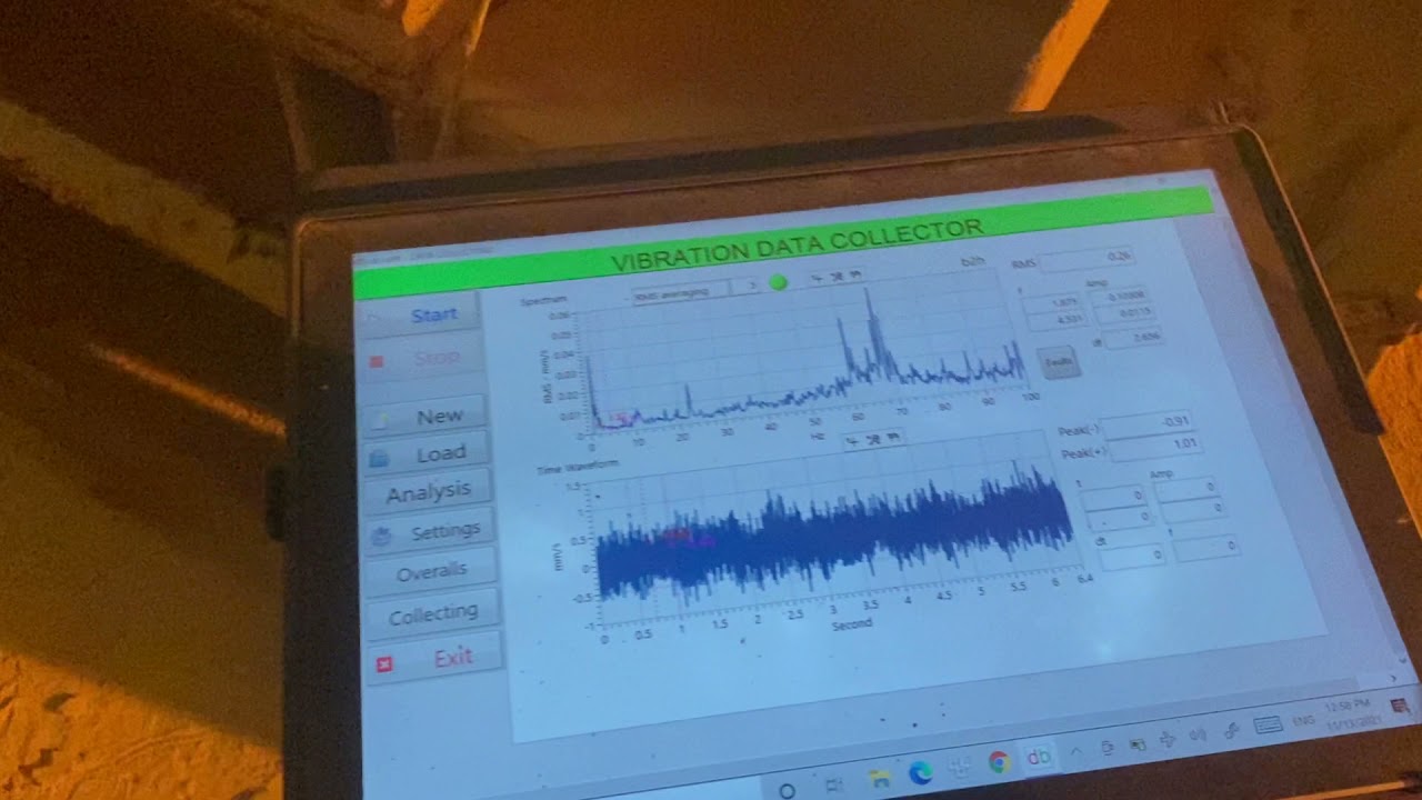
주제와 관련된 이미지 high sensitivity accelerometer
주제와 관련된 더 많은 사진을 참조하십시오 High sensitivity accelerometer CTC (AC133, 500 mV/g) for low speed. 댓글에서 더 많은 관련 이미지를 보거나 필요한 경우 더 많은 관련 기사를 볼 수 있습니다.
주제에 대한 기사 평가 high sensitivity accelerometer
- Author: Dien Nguyen
- Views: 조회수 83회
- Likes: 좋아요 2개
- Date Published: 2021. 11. 13.
- Video Url link: https://www.youtube.com/watch?v=JnJYvNBrnTw
What is sensitivity of accelerometer?
Accelerometer Sensitivity:
The ratio of change in acceleration (input) to change in the output signal. This defines the ideal, straight-line relationship between acceleration and output (Figure 1, gray line).
How do I choose an accelerometer sensitivity?
- Consider the type of measurement – vibration, motion, shock, or seismic.
- Type of acceleration – static or dynamic.
- Device size – handheld, medium, or heavy machinery.
- The environment – temperature and gravity can affect some accelerometers.
What is the most accurate accelerometer?
According to the National Institute of Standards and Technology (NIST) the optomechanical accelerometer has been more rigorously tested than similar devices and is much more precise than the best commercial accelerometers.
How do ICP accelerometers work?
Construction of ICP® Accelerometers
Under acceleration, the seismic mass causes stress on the sensing crystals which results in a proportional electrical output. The output is collected on electrodes and transmitted by wires connected to the microelectronic circuitry in ICP® accelerometers.
How do you increase the sensitivity of an accelerometer?
The sensitivity of the accelerometer is shown to increase under a large heating power. As shown in Figure 4b,c, increasing the heating power can raise the temperature difference in the cavity of the accelerometer, simultaneously providing high sensitivity.
What is 2g in accelerometer?
What is an Accelerometer? Accelerometers are devices that measure acceleration, which is the rate of change of the velocity of an object. They measure in meters per second squared (m/s2) or in G-forces (g).
What accelerometer should I use?
For most test environments, we recommend using an IEPE accelerometer with TEDS. An IEPE accelerometer powered by a constant current provides a clean signal and removes many of the noise sources that are common with other types of accelerometers.
What is XYZ accelerometer?
The accelerometer in the mobile device provides the XYZ coordinate values, which is used to measure the position and the acceleration of the device. The XYZ coordinate represents direction and position of the device at which acceleration occurred.
How accurate are accelerometers?
Across the studies, median sensitivity ranged from 46% to 96% and median specificity ranged from 71% to 96%. Median area under the curve ranged from 69% to 98%. Conclusions: Accuracy measures were greatest when detecting sedentary behavior and lowest when detecting light physical activity.
How accurate is the Iphone accelerometer?
Results: The mean difference between the app and the Biodex recordings was less than 1°/s for all test velocities. The coefficient of variation was less than 3% at velocities from 30°/s to 120°/s and less than 7% at 150°/s. Conclusions: The app was highly accurate and precise.
What is difference between gyroscope and accelerometer?
Accelerometer Versus Gyroscope
Accelerometers measure linear acceleration (specified in mV/g) along one or several axis. A gyroscope measures angular velocity (specified in mV/deg/s).
What is ADXL345 accelerometer?
The ADXL345 is a small, thin, low power, 3-axis accelerometer with high resolution (13-bit) measurement at up to ±16g. Digital output data is formatted as 16-bit twos complement and is accessible through either a SPI (3- or 4-wire) or I2C digital interface. The ADXL345 is well suited for mobile device applications.
What is the difference between ICP and IEPE?
IEPE is an initialism for Integrated Electronic Piezoelectric. Integrated Circuit-Piezoelectric, or ICP®, is a trademark of PCB Piezotronics, Inc., and refers specifically to the IEPE devices that they manufacture.
What is LVDT accelerometer?
The LVDT accelerometer consists of one primary winding and two secondary windings having an equal number of turns. Between the primary and two secondary windings, a core is placed which acts as a sensing mass. This core is connected to the housing of the accelerometer by means of two flexible reeds.
How does IEPE accelerometer work?
ICP is the trademarked PCB name for IEPE accelerometers. It stands for ‘Integrated circuit-piezo electric’. What is a charge output accelerometer? All piezo-electric accelerometers work by measuring the charge generated by a crystal that is being compressed or shear loaded by a mass influenced by acceleration.
How do you increase the sensitivity of a sensor?
1) Amplifiers will increase the sensitivity of a sensor. 2) Noise filters will increase the precision of a sensor.
What is the principle of accelerometer?
An accelerometer is a device that measures the vibration, or acceleration of motion of a structure. The force caused by vibration or a change in motion (acceleration) causes the mass to “squeeze” the piezoelectric material which produces an electrical charge that is proportional to the force exerted upon it.
What is accelerometer resolution?
Resolution
Resolution of an accelerometer is generally only given for digital output accelerometers or systems that incorporate an analog to digital converter. Resolution will typically be specified as bits which can then be used to calculate the resolution in acceleration units.
How do I change the sensitivity of my accelerometer Android?
Hold your device in your hand, wave it in the air in the pattern of a figure-eight a few times and then set the device back down on a flat surface. Accelerometer Sensor automatically re-adjusts the range of your accelerometer and can effectively calibrate your G-Sensor.
High Sensitivity Accelerometers
The piezoelectric accelerometers on this page are intended for the measurement of lowest vibrations. Typical fields of application include the monitoring of buildings, dams, bridges, oil platforms and pipelines. These sensors are often called seismic accelerometers because they are used to monitor construction activity, volcanoes and earthquakes. Their high sensitivity is achieved -unlike other high sensitivity accelerometers- by the sensing element itself and not by internal amplification. From this results highest resolution and lowest noise.Model KB12VD has an unusual design featuring air damping for a low resonance peak and friction coupling for overload protection.Cross-section of KB12VD:Useful technical information about piezoelectric accelerometers can be found on our Theory pages.For a selection chart to find the best sensor to your application click here An introduction to the measurement of vibration criteria for sensitive equipment is found on the Theory pages.
Accelerometer Specifications – Quick Definitions
Measurement Range:
The level of acceleration supported by the sensor’s output signal specifications, typically specified in ±g. This is the greatest amount of acceleration the part can measure and accurately represent as an output. For example, the output of a ±3g accelerometer is linear with acceleration up to ±3g. If it is accelerated at 4g, the output may rail. Note that the breaking point is specified by the Absolute Maximum Acceleration, NOT by the measurement range. A 4g acceleration will not break a ±3g accelerometer.
Accelerometer Sensitivity:
The ratio of change in acceleration (input) to change in the output signal. This defines the ideal, straight-line relationship between acceleration and output (Figure 1, gray line). Sensitivity is specified at a particular supply voltage and is typically expressed in units of mV/g for analog-output accelerometers, LSB/g, or mg/LSB for digital-output accelerometers. It is usually specified in a range (min, typ, max) or as a typical figure and % deviation. For analog-output sensors, sensitivity is ratiometric to supply voltage; doubling the supply, for example, doubles the sensitivity.
Sensitivity change due to Temperature is generally specified as a % change per °C. Temperature effects are caused by a combination of mechanical stresses and circuit temperature coefficients.
Figure 1. Nonlinearity is a measurement of the deviation of an accelerometer
response (illustrated in black) from a perfectly linear response (in gray). This
graph is for illustration purposes only and does not show real accelerometer data.
Nonlinearity:
Ideally, the relationship between voltage and acceleration is linear and described by the sensitivity of the device. Nonlinearity is a measurement of deviation from a perfectly constant sensitivity, specified as a percentage with respect to either full-scale range (%FSR) or ± full scale (%FS). Typically, FSR = FS+FS. Nonlinearity of Analog Devices accelerometers is low enough that it can most often be ignored.
Package Alignment Error:
The angle between the accelerometer-sensing axes and the referenced package feature (see Figure 2). “Input Axis Alignment” is another term used for this error. The units for package alignment error are “degrees.” Packaging technology typically aligns the die to within about 1° of the package.
(Orthogonal) Alignment Error:
The deviation from the ideal angular displacement (typically 90°) between multi-axis devices (see Figure 2). Analog Devices accelerometers are manufactured using photolithography on a single piece of silicon, so axis-to-axis alignment error is not generally a problem.
Cross-Axis Sensitivity:
A measure of how much output is seen on one axis when acceleration is imposed on a different axis, typically specified as a percentage. The coupling between two axes results from a combination of alignment errors, etching inaccuracies, and circuit crosstalk.
Zero-g Bias Level:
Specifies the output level when there is no acceleration (zero input). Analog sensors typically express this in volts (or mV) and digital sensors in codes (LSB). Zero-g Bias is specified at a particular supply voltage and is typically ratiometric with supply voltage (most often, zero-g bias is nominally half the supply voltage).
Several aspects of zero-g bias are often specified:
Zero-g Voltage , in V, specifies the range of voltages that may be expected at the output under 0g of acceleration.
, in V, specifies the range of voltages that may be expected at the output under 0g of acceleration. Output Deviation from Ideal , also called Initial Bias Error, is specified at 25°C, either in terms of acceleration error (g) or output signal: mV for analog sensors and LSB for digital sensors.
, also called Initial Bias Error, is specified at 25°C, either in terms of acceleration error (g) or output signal: mV for analog sensors and LSB for digital sensors. Zero-g Offset vs. Temperature , or Bias Temperature Coefficient , in mg/°C, describes how much the output shifts for each °C temperature change; and
, or , in mg/°C, describes how much the output shifts for each °C temperature change; and Bias Voltage Sensitivity is the change in “Zero-Bias Level” with respect to change in power supply. The units for this parameter are typically, mv/V, mg/V, or LSB/V.
is the change in “Zero-Bias Level” with respect to change in power supply. The units for this parameter are typically, mv/V, mg/V, or LSB/V. Zero-g Total Error includes all errors.
Acelerometer Noise Density:
In ug/rt(Hz) RMS, is the square root of the power spectral density of the noise output. Total noise is determined by the equation:
Noise = Noise Density * sqrt(BW * 1.6)
where BW is the accelerometer bandwidth, set by capacitors on the accelerometer outputs.
Analog Devices accelerometers’ noise is Gaussian and uncorrelated, so noise can be reduced by averaging the outputs from several accelerometers. supply voltage (most often, zero-g bias is nominally half the supply voltage).
Total Noise:
The random deviation from the ideal output and is equal to the multiplied product of the Noise Density and the square root of the Noise Bandwidth. The units for this parameter are typically mg-RMS.
Figure 2. Showing package alignment error α and sensor alignment
error θ. α is the angle between the sensor axes and the package axes.
θ is the deviation of the sensor axes from orthogonal, i.e., the
difference between (ysensor – xsensor) and 90°.
Output Data Rate:
In digital-output accelerometers, defines the rate at which data is sampled. Bandwidth is the highest frequency signal that can be sampled without aliasing by the specified Output Data Rate. Per the Nyquist sampling criterion, bandwidth is half the Output Data Rate.
In analog-output accelerometers, bandwidth is defined as the signal frequency at which the response falls to -3dB of the response to DC (or low-frequency) acceleration.
What to Look for When Selecting Accelerometers?
Consider the type of measurement – vibration, motion, shock, or seismic.
Type of acceleration – static or dynamic.
Device size – handheld, medium, or heavy machinery.
The environment – temperature and gravity can affect some accelerometers.
Measurement range and sensitivity of the accelerometer
Accelerometer Specifications
Dynamic Range is the +/- maximum amplitude that the accelerometer can measure before distorting or clipping the output signal. Typically specified in g’s.
Frequency Response is determined by the mass, the piezoelectric properties of the crystal, and the resonance frequency of the case. It is the frequency range where the output of the accelerometer is within a specified deviation, typically +/- 5%. g 1g is the acceleration due to the earth’s gravity which is 32.2 ft/sec2, 386 in/sec2 or 9.8 m/sec2.
Grounding – There are two types of signal grounding in accelerometers. Case Grounded accelerometers have the low side of the signal connected to their case. As the case is part of the signal path and may be attached to a conductive material, care must be used when using this type of accelerometer to avoid noise from the ground plain. Ground Isolated accelerometers have the electrical components isolated from the case and are much less susceptible to ground induced noise.
High Frequency Limit is the frequency where the output exceeds the stated output deviation. It is typically governed by the mechanical resonance of the accelerometer.
Low Frequency Cut-off is the frequency where the output starts to fall off below the stated accuracy. The output does not “cut-off ” but the sensitivity decreases rapidly with lower frequencies.
Noise – Electronic noise is generated by the amplifying circuit. Noise can be specified either broad band (specified over the a frequency spectrum) or spectral – designated at specific frequencies. Noise levels are specified in g’s, i.e. 0.0025 g 2-25,000 Hz. Noise typically decreases as frequency increases so noise at low frequencies is more of a problem than at high frequencies.
Sensitivity is the output voltage produced by a certain force measured in g’s. Accelerometers typically fall into two categories – producing either 10 mV/g or 100 mV/g. The frequency of the AC output voltage will match the frequency of the vibrations. The output level will be proportional to the amplitude of the vibrations. Low output accelerometers are used to measure high vibrational levels while high output accelerometers are used to measure low level vibrations.
Temperature Sensitivity is the voltage output per degree of measured temperature. The sensors are temperature compensated to keep the change in output to within the specified limits for a change in temperature.
Temperature Range is limited by the electronic micro circuit that converts the charge to a low impedance output. Typically the range is -50 to 120C. Other Considerations when choosing an Accelerometer:
The mass of the accelerometers should be significantly smaller than the mass of the system to be monitored. The accelerometer dynamic range should be broader than the expected vibration amplitude range of the sample. The frequency range of the accelerometer should fit the expected frequency range. The Sensitivity of the accelerometer should produce an electrical output compatible with existing instrumentation. Use a low sensitivity accelerometer to measure high amplitude vibrations and conversely use a high sensitivity accelerometer to measure low amplitude vibrations.
US researchers develop new type of highly accurate and reliable accelerometer
Researchers at the National Institute of Standards and Technology have developed an accelerometer one millimeter thick that uses laser light instead of mechanical strain to produce a signal.
Although a few other accelerometers also rely on light, the design of the optomechanical accelerometer makes the measuring process more straightforward, providing higher accuracy. It also operates over a greater range of frequencies and
‘) } else { console.log (‘nompuad’); document.write(‘ ‘) } // –> ‘) } else if (width >= 425) { console.log (‘largescreen’); document.write(”) } else { console.log (‘nompuad’); document.write(”) } // –>
According to the National Institute of Standards and Technology (NIST) the optomechanical accelerometer has been more rigorously tested than similar devices and is much more precise than the best commercial accelerometers. It also does not need to periodically calibrated.
The instrument’s use of laser light of a known frequency to measure acceleration could make it suitable for use as a portable reference standard to calibrate other accelerometers now on the market, making them more accurate.
The accelerometer also has the potential to improve inertial navigation in such critical systems as military aircraft, satellites and submarines, especially when a GPS signal is not available.
The animation below describes in more detail how the accelerometer works,
The accelerometer was developed as part of the NIST on a Chip, a program that aims to use the institute’s measurement-science technology and expertise for applications in commerce, medicine, defense and academia.
Accelerometers, including this new NIST accelerometer, record changes in velocity by tracking the position of a freely moving mass, dubbed the “proof mass,” relative to a fixed reference point inside the device. The motion of the proof mass creates a detectable signal.
The accelerometer developed by NIST researchers relies on infrared light to measure the change in distance between two highly reflective surfaces that bookend a small region of empty space. The proof mass, which is suspended by flexible beams one-fifth the width of a human hair so that it can move freely, supports one of the mirrored surfaces. The other reflecting surface, which serves as the accelerometer’s fixed reference point, consists of an immovable microfabricated concave mirror.
Together, the two reflecting surfaces and the empty space between them form a cavity in which infrared light of just the right wavelength can resonate, or bounce back and forth, between the mirrors, building in intensity. That wavelength is determined by the distance between the two mirrors, much as the pitch of a plucked guitar depends on the distance between the instrument’s fret and bridge. If the proof mass moves in response to acceleration, changing the separation between the mirrors, the resonant wavelength also changes.
To track the changes in the cavity’s resonant wavelength with high sensitivity, a stable single-frequency laser is locked to the cavity. The researchers have also employed an optical frequency comb — a device that can be used as a ruler to measure the wavelength of light — to measure the cavity length with high accuracy.
The markings of the ruler can be thought of as a series of lasers with equally spaced wavelengths. When the proof mass moves during a period of acceleration, either shortening or lengthening the cavity, the intensity of the reflected light changes as the wavelengths associated with the comb’s teeth move in and out of resonance with the cavity.
Accurately converting the displacement of the proof mass into an acceleration is a critical step that has been problematic in most existing optomechanical accelerometers. However, the team’s new design ensures that the dynamic relationship between the displacement of the proof mass and the acceleration is simple and easy to model. In short, the proof mass and supporting beams are designed so that they behave like a simple spring, or harmonic oscillator, that vibrates at a single frequency in the operating range of the accelerometer.
This simple dynamic response enabled the scientists to achieve low measurement uncertainty over a wide range of acceleration frequencies — 1 kilohertz to 20 kilohertz — without ever having to calibrate the device. Since the publication of their study in Optica, the researchers have made several improvements that should decrease their device’s uncertainty to nearly 1%.
Capable of sensing displacements of the proof mass that are less than one hundred-thousandth the diameter of a hydrogen atom, the optomechanical accelerometer detects accelerations as tiny as 32 billionths of a g, where g is the acceleration due to Earth’s gravity, a higher sensitivity than all accelerometers now on the market with similar size and bandwidth.
NIST researchers Jason Gorman, Thomas LeBrun, David Long and their colleagues describe their work in the journal Optica.
High-sensitivity accelerometer
… group function. Low sensitivity temperature drift,stability of the whole temperature area. CE certification. Explosion-proof certification. Applications: Hydropower, Thermal Power, Wind Power, Port Machinery, Bridge …
See the other products Monitran
See the other products Monitran
High sensitivity charge output top-entry accelerometer with TNC connector ideal for underground leak detection. This requires the use of a charge amplifier (for example, the MTN/CA003).
… navigation and clinical research. The new rugged VMU931 is a round IMU with a diameter of 31 mm, that can fit up to 3-axis accelerometers , 3-axis gyros, 3-axis magnetic, temperature sensors in a robust aluminum housing …
See the other products Sinocera Piezotronics INC.
See the other products Sinocera Piezotronics INC.
See the other products Althen Sensors & Controls
See the other products Althen Sensors & Controls
Single Axis Accelerometers One-axis Piezoelectric IEPE Acceleration Sensors are made of PZT ceramic and have a built-in charge-voltage converter and a pre-amplifier. High precision …
The piezoresistive accelerometer has a maximum sensitivity rate. It is designed for slow speed rotating machines, with a hydro turbines and fans. This product comes with the following specifications, …
See the other products DYTRAN INSTRUMENTS
See the other products DYTRAN INSTRUMENTS
The Dytran 3100D24 Ultra- high sensitive IEPE accelerometer . It includes a ceramic shear sensing element and a sensitivity rate of 1000 mV/g. The 5/8-inch hex casing is made with stainless …
Accelerometer PV_SERIES Rion “PV Series” piezoelectric accelerometers have a variety of types, for customers to choose the suitable one for their measurements. For example, we have lightweight type …
… Structures but also in the field of human engineering. Using a strain gage as the sensing element, AS-GA and AS-GB series acceleration transducers are designed to measure small levels of acceleration. The miniature lightweight …
See the other products Endevco
See the other products Endevco
… Ground isolated • 12 pC/g • General purpose and package-testing The Endevco® model 2223D is a triaxial piezoelectric accelerometer designed specifically for vibration measurement of three orthogonal axes on small …
Solgeo Models AFB Force Balance Accelerometers are high – sensitivity , low noise sensors designed for use in seismic and low level, low frequency motion studies. The accelerometers are …
Triaxial Accelerometers Properties • IEPE output • KS823B with high sensitivity , low frequency limit and very low noise, particularly suited for sensitive measurements at buildings …
High Sensitivity Accelerometers Properties • Suited for seismic measurement and building vibration, particularly at low frequencies • Extremely sensitive piezo system provides excellent …
High Sensitivity Accelerometers Properties • Suited for seismic measurement and building vibration, particularly at low frequencies • Extremely sensitive piezo system provides excellent …
See the other products Micromega
See the other products Micromega
Industrial Accelerometer (0…3V) The RECOVIB® industrial accelerometers bridge the gap between the performance of laboratory accelerometers (which are often expensive, fragile and …
See the other products Micromega
See the other products Micromega
Industrial Accelerometer (4-20 mA) The RECOVIB® industrial accelerometers bridge the gap between the performance of laboratory accelerometers (which are often expensive, fragile …
See the other products Micromega
See the other products Micromega
Industrial accelerometers The RECOVIB® industrial accelerometers bridge the gap between the performance of laboratory accelerometers (which are often expensive, fragile and offer low …
… Series Single axis Accelerometers Chips Product Introduction: AS100/AS200 MEMS Single axis Accelerometers Chips are developed and manufactured by BEWIS, which has completely independent intellectual …
MEMS accelerometer AS300 Product Introduction: AS300 is a high – sensitivity low-drift digital output tri-axis acceleration sensor developed by BEWIS Sensor. It is …
MEMS accelerometer AS400 Product Introduction: AS400 is a high – sensitivity low-drift digital output tri-axis acceleration sensor developed by BEWIS Sensor. It is …
HIGH -FREQUENCY PIEZOELECTRIC CHARGE ACCELEROMETER Piezoelectric charge accelerometer designed for high sensitivity and high frequency …
… threaded steel stud. USE SCENARIOS General purpose High sensitivity Low-level, low-frequency measurements This piezoelectric accelerometer may be treated as a charge source. …
{{#if product.newProduct}}{{/if}} {{#if product.hasVideo}}{{/if}}
{{#each product.specData:i}} {{name}} : {{value}} {{#i!=(product.specData.length-1)}} {{/end}} {{/each}}
{{product.productPrice.formattedPrice}} {{#if product.productPrice.priceType === “PRICE_RANGE” }} – {{product.productPrice.formattedPriceMax}} {{/if}}
not specified
not specified
Your answer has been taken into account. Thank-you for your help.
Your suggestions for improvement:
Evaluate the quality of the search results:
TELL US WHAT YOU THINK
Subscribe to our newsletter
Thank you for subscribing There was a problem with your request Invalid email address
Receive updates on this section every two weeks.
Please refer to our Privacy Policy for details on how DirectIndustry processes your personal data.
High Sensitivity Accelerometers
Product Overview
We provide a wide range of High Sensitivity Accelerometers manufactured by PCB Piezotronics. Piezoelectric accelerometers offer extreme versatility for both shock and vibration measurements. High Sensitivity ICP Accelerometers are specifically design to enable the detection of ultra low-level frequency vibrations, commonly associated with very large structures and foundations.
High Frequency ICP Accelerometers typically offer exceptional measurement resolution. Both ceramic and quartz sensing elements are utilized in seismic accelerometer designs. Quartz (Model 393C) sensing element offers the best low-frequency response in the series, while ceramic element offers the greatest measurement resolution.
All unites are hermetically sealed in either a titanium or stainless steel housing. Models that include a 2-pin military style connector provides the added benefit of being electrically case isolated for superior RF and EMI protection.
Please speak with our expert sales team for further information.
High-Sensitivity MEMS Accelerometer
High-Sensitivity MEMS Accelerometer
NEW MEMS Accelerometer Picks Up Ultra-Low Acceleration
Features
NTT Laboratories’ advanced microfabrication technologies are employed. *1
Ultra-high sensitivity and low noize is accomplished by optimal structure design.
*1 Japan Patent 5831905 (with Tokyo Institute of Technology) and Japan Patent 6044041 (with The University of Tokyo) are
granted for parts of the technologies.
Technical
Table. Main specifications (as of January, 2020).
Specifications may differ depending on the operating and environmental conditions.
Specifications may be subject to change without notice.
Customize service is available.
High-Sensitivity Accelerometer ANT-02/ANT-04 Data sheet Data sheet
To be applied to
Infrastructure/machine health monitoring, trouble predictin/prevention, human health monitoring and others.
Example: heart rate and breathing motion monitoring
Product Inquiry
키워드에 대한 정보 high sensitivity accelerometer
다음은 Bing에서 high sensitivity accelerometer 주제에 대한 검색 결과입니다. 필요한 경우 더 읽을 수 있습니다.
이 기사는 인터넷의 다양한 출처에서 편집되었습니다. 이 기사가 유용했기를 바랍니다. 이 기사가 유용하다고 생각되면 공유하십시오. 매우 감사합니다!
사람들이 주제에 대해 자주 검색하는 키워드 High sensitivity accelerometer CTC (AC133, 500 mV/g) for low speed
- 동영상
- 공유
- 카메라폰
- 동영상폰
- 무료
- 올리기
High #sensitivity #accelerometer #CTC #(AC133, #500 #mV/g) #for #low #speed
YouTube에서 high sensitivity accelerometer 주제의 다른 동영상 보기
주제에 대한 기사를 시청해 주셔서 감사합니다 High sensitivity accelerometer CTC (AC133, 500 mV/g) for low speed | high sensitivity accelerometer, 이 기사가 유용하다고 생각되면 공유하십시오, 매우 감사합니다.